SL811HS
5.2.8
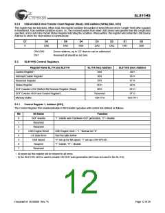
USB-A/USB-B Host Transfer Count Register (Read), USB Address (Write) [04H, 0CH]
This register has two functions. When read, this register contains the number of bytes left over (from “Length” field) after a packet
is transferred. If an overflow condition occurs, i.e., the received packet from slave USB device was greater than the Length field
specified, a bit is set in the Packet Status Register indicating the condition. When written, this register will contain the USB Device
Address to which the Host wishes to communicate.
D7
D6
D5
D4
D3
D2
D1
D0
0
DA6
DA5
DA4
DA3
DA2
DA1
DA0
DA6-DA0
DA7
Device address, up to 127 devices can be addressed
Reserved bit should be set zero.
5.3
SL811HS Control Registers
Register Name SL11H and SL811H
SL11H (hex) Address
SL811HS (hex) Address
Control Register1
05H
06H
05H
06 H
Interrupt Enable Register
Reserved Register
07H
07 H
Status Register
0DH
0DH
SOF Counter LOW (Write)/HW Revision Register (Read)
SOF Counter HIGH and Control Register2
Memory Buffer
0EH
0E H
Reserved
10H-FFH
0F H
10H-FFH
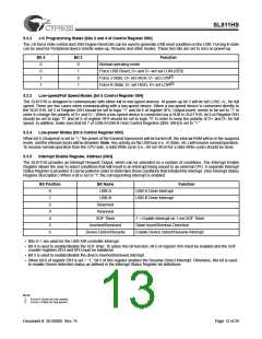
5.3.1
Control Register 1, Address [05H]
The Control Register 05H enables/disables USB transfer operation with control bits defined as follows.
Bit
0
Bit Name
SOF ena/dis
Reserved
Function
“1” enable auto Hardware SOF generation, “0”= disable
1
2
Reserved
3
USB Engine Reset
J-K state force
USB Speed
Suspend
USB Engine reset = “1.” Normal set “0”
See the table below
4
5
“0” set-up for full speed, “1” set-up LOW-SPEED
“1” enable, “0” = disable
6
7
Reserved
• At power-up this register will be cleared to all zeros.
• In the SL811HS, bit 0 is used to enable HW SOF auto-generation (bit 0 was not used in the SL11H).
Document #: 38-08008 Rev. *A
Page 12 of 29

 CYPRESS [ CYPRESS ]