CY8C9520A, CY8C9540A
CY8C9560A
Watchdog Register (2Fh)
Write E2 POR Defaults Cmd (03h)
This register controls the internal Watchdog timer. This timer can
trigger a device reset if the device is not responding to I2C
requests due to misconfiguration. Device operation is not
affected when the Watchdog register = 0. If the I2C master writes
any non zero value to the Watchdog register, the countdown
mechanism is activated and each second the register is decre-
mented. Upon transition from 1 to 0, the device is rebooted,
which restores user defaults. After reboot, the Watchdog register
value is reset to zero. Any I2C transaction (addressing the
Expander) resets the Watchdog register to the previously stored
value. Any device reboot (caused by a POR or Watchdog) sets
the Watchdog register to zero (turns off the Watchdog feature).
The Watchdog timer can be disabled by writing zero to the
Watchdog register (2Fh) or by using the Reconfigure Device
Cmd (07h).
This command sends new power up defaults to the CY8C95xx
without changing current settings unless the 07h command is
issued afterwards. This command is followed by 147 data bytes
according to Table 16. The CRC is calculated as the XOR of the
146 data bytes (00h-91h). If the CRC check fails or an incom-
plete block is sent, then the slave responds with a NAK and the
data does not get saved to EEPROM.
To define new POR defaults the user must:
■ Write command 03h
■ Write 146 data bytes with new values of registers
■ Write 1 CRC byte calculated as XOR of previous 146 data
bytes.
Content of the data block is described in Table 16.
Note The Watchdog timer is not intended to track precise time
intervals. The timer's frequency can vary in range between -50%
on up to +100%. This variation must be taken into account when
selecting the appropriate value for the Watchdog register.
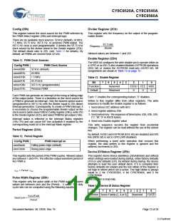
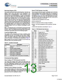
Table 16. POR Defaults Data Structure
Offset
00h – 07h
08h – 0Fh
10h – 17h
18h – 1Fh
20h – 27h
28h
Value
Output Port 0-7
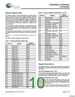
Command Register (30h)
Interrupt mask Port 0-7
Select PWM Port 0-7
Inversion Port 0-7
This register sends commands to the device, including current
configuration as new POR defaults, restore factory defaults,
define POR defaults, read POR defaults, write device configu-
ration, read device configuration, and reconfigure device with
stored POR defaults. The command set is presented in Table 15.
Pin Direction Port 0-7
Resistive pull up Drive Mode Port 0
Resistive pull down Drive Mode Port 0
Open drain high Drive Mode Port 0
Open drain low Drive Mode Port 0
Strong drive Drive Mode Port 0
Slow strong drive Drive Mode Port 0
High impedance Drive Mode Port 0
Drive Modes Port 1
Note Registers are not restored in parallel. Do not assume any
particular order to the restoration process.
29h
2Ah
Table 15. Available Commands
2Bh
Command
Description
2Ch
01h
Store device configuration to EEPROM POR
defaults
2Dh
2Eh
02h
03h
04h
05h
06h
07h
Restore Factory Defaults
2Fh – 35h
36h – 3Ch
3Dh – 43h
44h – 4Ah
4Bh – 51h
52h – 58h
59h – 5Fh
60h
Write EEPROM POR defaults
Read EEPROM POR defaults
Write device configuration
Drive Modes Port 2
Drive Modes Port 3
Drive Modes Port 4
Read device configuration
Drive Modes Port 5
Reconfigure device with stored POR defaults
Drive Modes Port 6
Drive Modes Port 7
Commands Description
Store Config to E2 POR Defaults Cmd (01h)
Config setting PWM0
Period setting PWM0
Pulse Width setting PWM0
PWM1 settings
61h
The current ports settings (drive modes and output data) and
other configuration registers are saved in the EEPROM by using
the store configuration command (Cmd). These settings are
automatically loaded after the next device power up or if the 07h
command is issued.
62h
63h – 65h
…
…
8Dh – 8Fh
90h
PWM15 settings
Restore Factory Defaults Cmd (02h)
Divider
This command replaces the saved user configuration with the
factory default configuration. Current settings are unaffected by
this command. New settings are loaded after the next device
power up or if the 07h command is issued.
91h
Enable
92h
CRC
Document Number: 38-12036 Rev. *B
Page 13 of 24
[+] Feedback

 CYPRESS [ CYPRESS ]