CY8C9520A, CY8C9540A
CY8C9560A
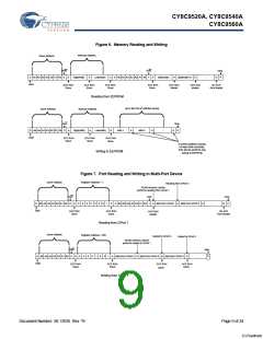
See Figure 7 on page 9 illustrates port read/write procedures.
The Inversion registers have no effect on these ports.
The Input registers' logic is presented in Table 9. These registers
have no effect on outputs or PWMs.
Int. Status Port Registers (10h - 17h)
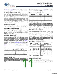
Table 9. Inversion Register Logic
Each ’1’ bit in these registers signals that there was a change in
the corresponding input line since the last read of that Interrupt
Status register. Each Interrupt (Int.) Status register is cleared
only after a read of that register.
Pin State
Invert
Input
0
1
0
1
0
0
1
1
0
1
1
0
If a PWM is assigned to a pin, then all state changes of the PWM
sets the corresponding bit in the Interrupt Status register. If the
pin's interrupt mask is cleared and the PWM is set to the slowest
possible rate allowed (driven by the programmable clock source
with divide register 2Dh set to FFh), then the INT line also drives
on the PWM state change.
Port Direction Register (1Ch)
Each bit in a port is configurable as either an input or an output.
To perform this configuration, the Port Direction register (1Ch) is
used for the GPort selected by the Port Select register (18h). If
a bit in this register is set (written with '1'), the corresponding port
pin is enabled as an input. If a bit in this register is cleared (written
with '0'), the corresponding port pin is enabled as an output.
Port Select Register (18h)
This register configures the GPort. Write a value of 0-7 to this
register to select the port to program with registers 19h-23h.
Interrupt Mask Port Register (19h)
Drive Mode Registers (1Dh-23h)
The Interrupt Mask register enables or disables activation of the
INT line when GPIO input levels are changed. Each ’1’ in the
Interrupt Mask register masks (disables) interrupts generated
from the corresponding input line of the GPort selected by the
Port Select register (18h).
Each port's data pins can be set separately to one of seven
available modes: pull up or down, open drain high/low, strong
drive fast/slow, or high-impedance input. To perform this config-
uration, the seven drive mode registers are used for the GPort
selected by the Port Select register (18h). Each ’1’ written to this
register changes the corresponding line drive mode. Registers
1Dh through 23h have last register priority meaning that the bit
set to high in which the last register was written overrides those
that came before. Reading these registers reflects the actual
setting, not what was originally written.
Select PWM Register (1Ah)
This register allows each port to act as a PWM output. By default,
all ports are configured as GPIO lines. Each ’1’ in this register
connects the corresponding pin of the GPort selected by the Port
Select register (18h) to the PWM output. Output register data
also affects the pin state when a PWM is enabled. See Table 8.
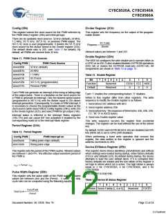
Table 10. Drive Mode Register Settings
Note that a pin used as PWM output must be configured to the
appropriate drive mode. See Table 10 on page 11 for more infor-
mation.
Reg.
1Dh
Pin State
Description
Resistive Pull Up
Resistive High, Strong Low
(default)
Table 8 describes the logic of the Output and Select PWM
registers.
1Eh
1Fh
20h
21h
Resistive Pull Down Strong High, Resistive Low
Table 8. Output and Select PWM Registers Logic
Open Drain High
Open Drain Low
Strong Drive
Slow Strong High, High Z Low
Slow Strong Low, High Z High
Output
Select PWM
Pin State
Strong High, Strong Low, Fast
Output Mode
0
1
0
1
0
0
1
1
0
1
22h
23h
Slow Strong Drive Strong High, Strong Low,
Slow Output Mode
0
Current PWM
High Impedance
High Z
Inversion Register (1Bh)
This register can invert the logic of the input ports. Each ’1’
written to this register inverts the logic of the corresponding bit in
the Input register of the GPort selected by the Port Select register
(18h).
PWM Select Register (28h)
This register is configures the PWM. Write a value of 00h-0Fh to
this register to select the PWM to program with registers
29h-2Bh.
Document Number: 38-12036 Rev. *B
Page 11 of 24
[+] Feedback

 CYPRESS [ CYPRESS ]