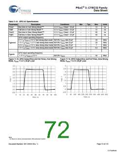
PSoC® 3: CY8C32 Family
Data Sheet
11.1.3 USBIO
For operation in GPIO mode, the standard range for VDDD applies, see Device Level Specifications on page 63.
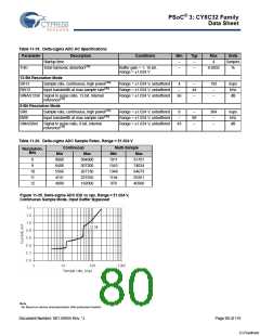
Table 11-13. USBIO DC Specifications
Parameter
Rusbi
Description
USB D+ pull-up resistance
USB D+ pull-up resistance
Static output high
Conditions
With idle bus
Min
0.900
1.425
2.8
Typ
–
Max
1.575
3.090
3.6
Units
kΩ
Rusba
While receiving traffic
–
kΩ
Vohusb
15 kΩ ±5% to Vss, internal pull-up
enabled
–
V
Volusb
Static output low
15 kΩ ±5% to Vss, internal pull-up
enabled
–
–
0.3
V
Vohgpio
Volgpio
Vdi
Output voltage high, GPIO mode
Output voltage low, GPIO mode
Differential input sensitivity
I
I
OH = 4 mA, VDDD ≥ 3 V
OL = 4 mA, VDDD ≥ 3 V
2.4
–
–
–
–
–
–
V
V
V
V
0.3
0.2
2.5
|(D+)–(D–)|
–
–
Vcm
Differential input common mode
range
0.8
Vse
Single ended receiver threshold
PS/2 pull-up resistance
–
0.8
3
–
–
2
7
V
Rps2
In PS/2 mode, with PS/2 pull-up
enabled
kΩ
External USB series resistor
In series with each USB pin
21.78
(–1%)
22
22.22
(+1%)
Ω
Rext
Zo
USB driver output impedance
Including Rext
28
–
–
–
–
44
20
2
Ω
CIN
USB transceiver input capacitance –
pF
nA
Input leakage current (absolute
value)
25 °C, VDDD = 3.0 V
–
IIL
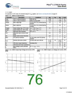
Figure 11-22. USBIO Output High Voltage and Current, GPIO
Mode
Figure 11-23. USBIO Output Low Voltage and Current, GPIO
Mode
Document Number: 001-56955 Rev. *J
Page 76 of 119
[+] Feedback

 CYPRESS [ CYPRESS ]