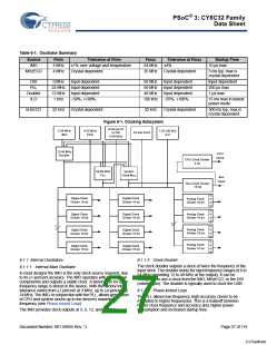
PSoC® 3: CY8C32 Family
Data Sheet
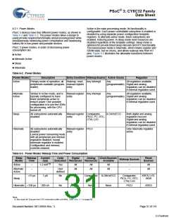
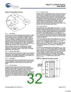
6.2.1 Power Modes
Active is the main processing mode. Its functionality is
configurable. Each power controllable subsystem is enabled or
disabled by using separate power configuration template
registers. In alternate active mode, fewer subsystems are
enabled, reducing power. In sleep mode most resources are
disabled regardless of the template settings. Sleep mode is
optimized to provide timed sleep intervals and RTC functionality.
The lowest power mode is hibernate, which retains register and
SRAM state, but no clocks, and allows wakeup only from I/O
pins. Figure 6-5 illustrates the allowable transitions between
power modes.
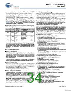
PSoC 3 devices have four different power modes, as shown in
Table 6-2 and Table 6-3. The power modes allow a design to
easily provide required functionality and processing power while
simultaneously minimizing power consumption and maximizing
battery life in low-power and portable devices.
PSoC 3 power modes, in order of decreasing power
consumption are:
Active
Alternate Active
Sleep
Hibernate
Table 6-2. Power Modes
Power Modes
Description
EntryCondition WakeupSource Active Clocks
Regulator
Active
Primary mode of operation, all Wakeup, reset, Any interrupt
peripherals available (program- manual register
Any
All regulators available.
(programmable) Digital and analog
mable)
entry
regulators can be disabled
if external regulation used.
All regulators available.
Alternate
Active
Similar to Active mode, and is
typically configured to have
fewer peripherals active to
reduce power. One possible
configuration is to use the UDBs
for processing, with the CPU
turned off
Manual register Any interrupt
entry
Any
(programmable) Digital and analog
regulators can be disabled
if external regulation used.
Sleep
All subsystems automatically
disabled
Manual register Comparator,
entry
ILO/kHzECO
Both digital and analog
regulators buzzed.
Digital and analog
PICU, I2C, RTC,
CTW, LVD
regulators can be disabled
if external regulation used.
Hibernate
All subsystems automatically
disabled
Manual register PICU
entry
Only hibernate regulator
active.
Lowest power consuming mode
with all peripherals and internal
regulators disabled, except
hibernate regulator is enabled
Configuration and memory
contents retained
Table 6-3. Power Modes Wakeup Time and Power Consumption
Sleep
Modes
Wakeup
Time
Current
(typ)
Code
Digital
Analog
ClockSources
Reset
Sources
Wakeup Sources
Execution Resources Resources
Available
Active
–
–
1.2 mA[12]
Yes
All
All
All
All
All
All
–
–
All
All
Alternate
Active
–
User
defined
<15 µs
1 µA
No
I2C
Comparator ILO/kHzECO
Comparator,
PICU, I2C, RTC,
CTW, LVD
XRES, LVD,
WDR
Sleep
Hibernate <100 µs
200 nA
No
None
None
None
PICU
XRES
Note
12. Bus clock off. Execute from CPU instruction buffer at 6 MHz. See Table 11-2 on page 63.
Document Number: 001-56955 Rev. *J
Page 31 of 119
[+] Feedback

 CYPRESS [ CYPRESS ]