PSoC® 3: CY8C32 Family
Data Sheet
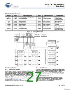
Table 6-1. Oscillator Summary
Source
IMO
Fmin
3 MHz
4 MHz
Tolerance at Fmin
±1% over voltage and temperature
Crystal dependent
Fmax
24 MHz
25 MHz
Tolerance at Fmax
±4%
Startup Time
10 µs max
MHzECO
Crystal dependent
5 ms typ, max is
crystal dependent
DSI
PLL
0 MHz
Input dependent
50 MHz
50 MHz
48 MHz
100 kHz
Input dependent
Input dependent
Input dependent
–55%, +100%
Input dependent
250 µs max
1 µs max
24 MHz Input dependent
12 MHz Input dependent
Doubler
ILO
1 kHz
–50%, +100%
15 ms max in lowest
power mode
kHzECO
32 kHz
Crystal dependent
32 kHz
Crystal dependent
500 ms typ, max is
crystal dependent
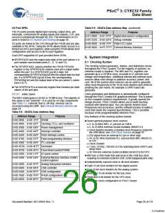
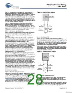
Figure 6-1. Clocking Subsystem
External IO
or DSI
0-50 MHz
3-24 MHz
IMO
4-25 MHz
ECO
1,33,100 kHz
ILO
32 kHz ECO
12-48 MHz
Doubler
CPU
Clock
CPU Clock Divider
4 bit
24-50 MHz
PLL
System
Clock Mux
Bus
Clock
Bus Clock Divider
16 bit
s
k
e
w
Digital Clock
Divider 16 bit
Digital Clock
Divider 16 bit
Analog Clock
Divider 16 bit
s
k
e
w
Digital Clock
Divider 16 bit
Digital Clock
Divider 16 bit
Analog Clock
Divider 16 bit
7
s
k
e
w
7
Analog Clock
Divider 16 bit
Digital Clock
Divider 16 bit
Digital Clock
Divider 16 bit
s
k
e
w
Analog Clock
Divider 16 bit
Digital Clock
Divider 16 bit
Digital Clock
Divider 16 bit
6.1.1 Internal Oscillators
6.1.1.1 Internal Main Oscillator
6.1.1.2 Clock Doubler
The clock doubler outputs a clock at twice the frequency of the
input clock. The doubler works for input frequency ranges of 6 to
24 MHz (providing 12 to 48 MHz at the output). It can be
configured to use a clock from the IMO, MHzECO, or the DSI
(external pin). The doubler is typically used to clock the USB.
In most designs the IMO is the only clock source required, due
to its ±1-percent accuracy. The IMO operates with no external
components and outputs a stable clock. A factory trim for each
frequency range is stored in the device. With the factory trim,
tolerance varies from ±1 percent at 3 MHz, up to ±4-percent at
24 MHz. The IMO, in conjunction with the PLL, allows generation
of CPU and system clocks up to the device's maximum
frequency (see Phase-locked Loop)
6.1.1.3 Phase-locked Loop
The PLL allows low-frequency, high-accuracy clocks to be
multiplied to higher frequencies. This is a tradeoff between
higher clock frequency and accuracy and, higher power
consumption and increased startup time.
The IMO provides clock outputs at 3, 6, 12, and 24 MHz.
Document Number: 001-56955 Rev. *J
Page 27 of 119
[+] Feedback

 CYPRESS [ CYPRESS ]