PSoC® 3: CY8C32 Family
Data Sheet
security is needed in your application. The PSoC device also
offers an advanced security feature called Device Security which
permanently disables all test, programming, and debug ports,
protecting your application from external access (see the
“Device Security” section on page 60). For more information
about how to take full advantage of the security features in
PSoC, see the PSoC 3 TRM.
5. Memory
5.1 Static RAM
CY8C32 Static RAM (SRAM) is used for temporary data storage.
Up to 8 KB of SRAM is provided and can be accessed by the
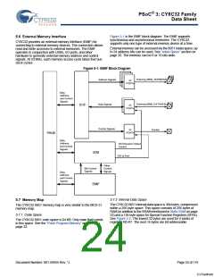
8051 or the DMA controller. See Memory Map on page 24.
Simultaneous access of SRAM by the 8051 and the DMA
controller is possible if different 4-KB blocks are accessed.
Table 5-1. Flash Protection
Protection
Setting
5.2 Flash Program Memory
Allowed
Not Allowed
Flash memory in PSoC devices provides nonvolatile storage for
user firmware, user configuration data, bulk data storage, and
optional ECC data. The main flash memory area contains up to
64 KB of user program space.
Unprotected
External read and write
+ internal read and write
–
Factory
Upgrade
External write + internal External read
read and write
Up to an additional 8 KB of flash space is available for Error
Correcting Codes (ECC). If ECC is not used this space can store
device configuration data and bulk user data. User code may not
be run out of the ECC flash memory section. ECC can correct
one bit error and detect two bit errors per 8 bytes of firmware
memory; an interrupt can be generated when an error is
detected.
Field Upgrade Internal read and write External read and
write
Full Protection Internal read
External read and
write + internal write
Disclaimer
Flash is read in units of rows; each row is 9 bytes wide with 8
bytes of data and 1 byte of ECC data. When a row is read, the
data bytes are copied into an 8-byte instruction buffer. The CPU
fetches its instructions from this buffer, for improved CPU
performance.
Note the following details of the flash code protection features on
Cypress devices.
Cypress products meet the specifications contained in their
particular Cypress datasheets. Cypress believes that its family of
products is one of the most secure families of its kind on the
market today, regardless of how they are used. There may be
methods, unknown to Cypress, that can breach the code
protection features. Any of these methods, to our knowledge,
would be dishonest and possibly illegal. Neither Cypress nor any
other semiconductor manufacturer can guarantee the security of
their code. Code protection does not mean that we are
guaranteeing the product as “unbreakable.”
Flash programming is performed through a special interface and
preempts code execution out of flash. The flash programming
interface performs flash erasing, programming and setting code
protection levels. Flash in-system serial programming (ISSP),
typically used for production programming, is possible through
both the SWD and JTAG interfaces. In-system programming,
typically used for bootloaders, is also possible using serial
interfaces such as I2C, USB, UART, and SPI, or any
communications protocol.
Cypress is willing to work with the customer who is concerned
about the integrity of their code. Code protection is constantly
evolving. We at Cypress are committed to continuously
improving the code protection features of our products.
5.3 Flash Security
All PSoC devices include a flexible flash-protection model that
prevents access and visibility to on-chip flash memory. This
prevents duplication or reverse engineering of proprietary code.
Flash memory is organized in blocks, where each block contains
256 bytes of program or data and 32 bytes of ECC or
configuration data. A total of up to 256 blocks is provided on
64-KB flash devices.
5.4 EEPROM
PSoC EEPROM memory is a byte-addressable nonvolatile
memory. The CY8C32 has up to 2 KB of EEPROM memory to
store user data. Reads from EEPROM are random access at the
byte level. Reads are done directly; writes are done by sending
write commands to an EEPROM programming interface. CPU
code execution can continue from flash during EEPROM writes.
EEPROM is erasable and writeable at the row level. The
EEPROM is divided into 128 rows of 16 bytes each.
The device offers the ability to assign one of four protection
levels to each row of flash. Table 5-1 lists the protection modes
available. Flash protection levels can only be changed by
performing a complete flash erase. The Full Protection and Field
Upgrade settings disable external access (through a debugging
tool such as PSoC Creator, for example). If your application
requires code update through a boot loader, then use the Field
Upgrade setting. Use the Unprotected setting only when no
The CPU can not execute out of EEPROM. There is no ECC
hardware associated with EEPROM. If ECC is required it must
be handled in firmware.
Document Number: 001-56955 Rev. *J
Page 22 of 119
[+] Feedback

 CYPRESS [ CYPRESS ]