PSoC® 3: CY8C32 Family
Data Sheet
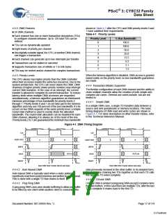
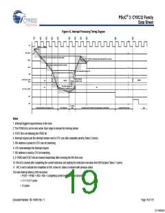
Figure 4-2. Interrupt Processing Timing Diagram
1
2
3
4
5
6
7
8
9
10
11
S
CLK
Arrival of new Interrupt
INT_INPUT
PEND
S
S
S
Pend bit is set on next system clock active edge
Interrupt is posted to ascertain the priority
POST and PEND bits cleared after IRQ is sleared
POST
IRQ
IRQ cleared after receiving IRA
Interrupt request sent to core for processing
S
S
The active interrupt
number is posted to core
ACTIVE_INT_NUM
(#10)
0x0000
NA
NA
0x0010
S
S
The active interrupt ISR
address is posted to core
NA
INT_VECT_ADDR
S
S
S
IRA
IRC
Int. State
Clear
Interrupt generation and posting to CPU
CPU Response
Completing current instruction and branching to vector address
Complete ISR and return
TIME
Notes
1: Interrupt triggered asynchronous to the clock
2: The PEND bit is set on next active clock edge to indicate the interrupt arrival
3: POST bit is set following the PEND bit
4: Interrupt request and the interrupt number sent to CPU core after evaluation priority (Takes 3 clocks)
5: ISR address is posted to CPU core for branching
6: CPU acknowledges the interrupt request
7: ISR address is read by CPU for branching
8, 9: PEND and POST bits are cleared respectively after receiving the IRA from core
10: IRA bit is cleared after completing the current instruction and starting the instruction execution from ISR location (Takes 7 cycles)
11: IRC is set to indicate the completion of ISR, Active int. status is restored with previous status
The total interrupt latency (ISR execution)
= POST + PEND + IRQ + IRA + Completing current instruction and branching
= 1+1+1+2+7 cycles
= 12 cycles
Document Number: 001-56955 Rev. *J
Page 19 of 119
[+] Feedback

 CYPRESS [ CYPRESS ]