PSoC® 3: CY8C32 Family
Data Sheet
11.5.3 Interrupt Controller
Table 11-60. Interrupt Controller AC Specifications
Parameter
Description
Conditions
Min
Typ
Max
Units
Delay from interrupt signal input to ISR Includes worse case completion of
–
–
25
Tcy CPU
code execution from ISR code
longest instruction DIV with 6
cycles
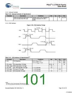
11.5.4 JTAG Interface
Figure 11-55. JTAG Interface Timing
(1/f_TCK)
TCK
TDI
T_TDI_setup
T_TDI_hold
T_TDO_hold
T_TDO_valid
TDO
TMS
T_TMS_setup
T_TMS_hold
Table 11-61. JTAG Interface AC Specifications[46]
Parameter Description
f_TCK TCK frequency
Conditions
3.3 V ≤ VDDD ≤ 5 V
Min
Typ
–
Max
14[47]
7[47]
–
Units
MHz
MHz
ns
–
1.71 V ≤ VDDD < 3.3 V
–
(T/10) – 5
T/4
–
T_TDI_setup
TDI setup before TCK high
–
T_TMS_setup TMS setup before TCK high
–
–
T_TDI_hold
T_TDO_valid
T_TDO_hold
TDI, TMS hold after TCK high
TCK low to TDO valid
T = 1/f_TCK max
T = 1/f_TCK max
T = 1/f_TCK max
T/4
–
–
–
–
2T/5
–
TDO hold after TCK high
T/4
–
Notes
46. Based on device characterization (Not production tested).
47. f_TCK must also be no more than 1/3 CPU clock frequency.
Document Number: 001-56955 Rev. *J
Page 101 of 119
[+] Feedback

 CYPRESS [ CYPRESS ]