CY7C64013
CY7C64113
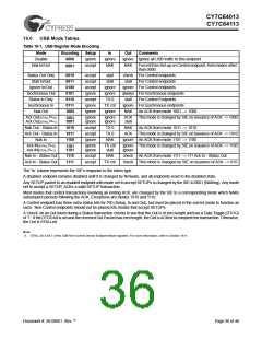
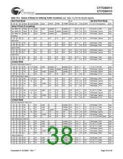
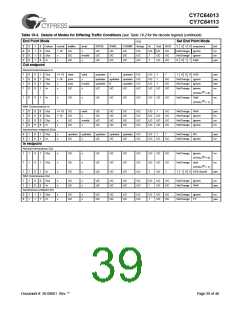
Table 19-2. Decode table for Table 19-3: “Details of Modes for Differing Traffic Conditions”
Properties of incoming packet
Encoding
Status bits
What the SIE does to Mode bits
PID Status bits
Interrupt?
End Point
Mode
End Point Mode
3
2
1
0
Token
Setup
In
count
buffer
dval
DTOG
DVAL
COUNT
Setup
In
Out
ACK
3
2
1
0
Response Int
Out
The validity of the received data
The quality status of the DMA buffer
The number of received bytes
Acknowledge phase completed
Legend:
UC: unchanged
TX: transmit
RX: receive
TX0: transmit 0-length packet
x: don’t care
available for Control endpoint only
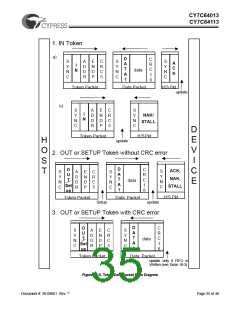
The response of the SIE can be summarized as follows:
1. The SIE only responds to valid transactions and ignores non-valid ones.
2. The SIE generates an interrupt when a valid transaction is completed or when the FIFO is corrupted. FIFO corruption occurs
during an OUT or SETUP transaction to a valid internal address that ends with a non-valid CRC.
3. An incoming Data packet is valid if the count is < Endpoint Size + 2 (includes CRC) and passes all error checking.
4. An IN is ignored by an OUT configured endpoint and vice versa.
5. The IN and OUT PID status is updated at the end of a transaction.
6. The SETUP PID status is updated at the beginning of the Data packet phase.
7. The entire Endpoint 0 mode register and the count register are locked from CPU writes at the end of any transaction to that
endpoint in which either an ACK is transferred or the mode bits have changed. These registers are only unlocked by a CPU
read of these registers, and only if that read happens after the transaction completes. This represents about a 1-µs window
in which the CPU is locked from register writes to these USB registers. Normally, the firmware should perform a register read
at the beginning of the Endpoint ISRs to unlock and get the mode register information. The interlock on the Mode and Count
registers ensures that the firmware recognizes the changes that the SIE might have made during the previous transaction.
Document #: 38-08001 Rev. **
Page 37 of 48

 CYPRESS [ CYPRESS ]