12.10 I2C Registers
I2C Control and Status
I2CS
7FA5
b7
b6
b5
b4
b3
b2
b1
b0
START
STOP
LASTRD
ID1
ID0
BERR
ACK
DONE
R/W
0
R/W
0
R/W
0
R
x
R
x
R
0
R
0
R
0
I2C Data
I2DAT
7FA6
b7
b6
b5
b4
b3
b2
b1
b0
D7
D6
D5
D4
D3
D2
D1
D0
R/W
x
R/W
x
R/W
x
R/W
x
R/W
x
R/W
x
R/W
x
R/W
x
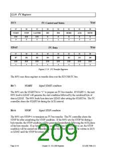
Figure 12-14. I2C Transfer Registers
The 8051 uses these registers to transfer data over the EZ-USB I2C bus.
Bit 7:
START
Signal START condition
The 8051 sets the START bit to “1” to prepare an I2C bus transfer. If START=1, the next
8051 load to I2DAT will generate the start condition followed by the serialized byte of
data in I2DAT. The 8051 loads byte data into I2DAT after setting the START bit. The I2C
controller clears the START bit during the ACK interval.
Bit 6:
STOP
Signal STOP condition
The 8051 sets STOP=1 to terminate an I2C bus transfer. The I2C controller clears the
STOP bit after completing the STOP condition. If the 8051 sets the STOP bit during a
byte transfer, the STOP condition will be generated immediately following the ACK phase
of the byte transfer. If no byte transfer is occurring when the STOP bit is set, the STOP
condition will be carried out immediately on the bus. Data should not be written to I2CS
or I2DAT until the STOP bit returns low.
Page 12-16
Chapter 12. EZ-USB Registers
EZ-USB TRM v1.9

 CYPRESS [ CYPRESS ]