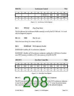
ISOCTL
Isochronous Control
7FA1
b7
b6
b5
b4
b3
b2
b1
b0
-
-
-
-
PPSTAT
MBZ
MBZ
ISODISAB
R
0
R
0
R
0
R
0
R
0
R/W
0
R/W
0
R/W
0
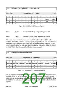
Figure 12-12. Isochronous Control Register
Bit 3:
PPSTAT
Ping-Pong Status
This bit indicates the isochronous buffer currently in use by the EZ-USB core. It is used
only for diagnostic purposes.
Bits 2,1:
These bits must always be written with zeros.
Bit 0: ISODISAB ISO Endpoints Disable
MBZ
Must be zero
ISODISAB=0 enables all 16 isochronous endpoints
ISODISAB=1 disables all 16 isochronous endpoints, making the 2,048 bytes of isochro-
nous FIFO memory available as 8051 data memory at 0x2000-0x27FF.
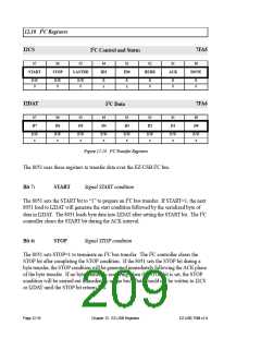
ZBCOUT
Zero Byte Count Bits
7FA2
b7
b6
b5
b4
b3
b2
b1
b0
EP15
EP14
EP13
EP12
EP11
EP10
EP9
EP8
R
x
R
x
R
x
R
x
R
x
R
x
R
x
R
x
Figure 12-13. Zero Byte Count Register
Bits 0-7:
EP(n)
Zero Byte Count for ISO OUT Endpoints
The 8051 can check these bits as a fast way to check all of the OUT isochronous endpoints
at once for no data received during the previous frame. A “1” in any bit position means
that a zero byte Isochronous OUT packet was received for the indicated endpoint.
EZ-USB TRM v1.9
Chapter 12. EZ-USB Registers
Page 12-15

 CYPRESS [ CYPRESS ]