Application Information ......
Rx Signal Path Description
The function of the Rx circuitry is to:
1. Set the incoming signal to a usable level.
2. Clean the signal by filtering.
3. Provide dc level thresholds for clock and data
extraction.
4. Provide clock timing information for data
extraction and external circuits.
5. Provide Rx data in a binary form.
6. Assess signal quality and provide Signal-to-Noise
information.
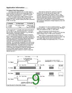
Positive going signal excursions at Rx Feedback
pin will produce a logic “0” at the Rx Data Output.
Negative going excursions will produce a logic “1.”
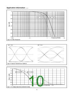
The received signal is fed through the lowpass Rx
Filter, which has a -3dB corner frequency of 0.56 times
the data bit-rate, before being applied to the Level
Measure and Clock and Data extraction blocks.
The Level Measuring block consists of two voltage
detectors. One of which measures the amplitude of the
‘positive’ parts of the received signal; the other
measures the amplitude of the ‘negative’ portions.
External capacitors are used by these detectors, via
the Doc 1/2 pins, to form voltage- ‘hold’ or ‘integrator’
circuits. Results of the two measurements are then
processed to establish the optimum dc level decision-
thresholds for the Clock and Data extraction,
depending upon the Rx signal amplitude, BT and any
dc offset present.
The output of the radio receiver's Frequency
Discriminator should be fed to the FX589's Rx Filter via
a suitable gain and dc level adjusting circuit. This gain
circuit can be built, with external components, around
the on-chip Rx Input Amplifier, with the gain set so that
the signal level at the Rx Feedback pin is nominally 1
Volt peak-to-peak (for VDD = 5.0 V) centred around
VBIAS when receiving a continuous “1111000011110... ”
data pattern.
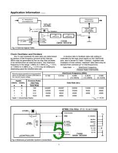
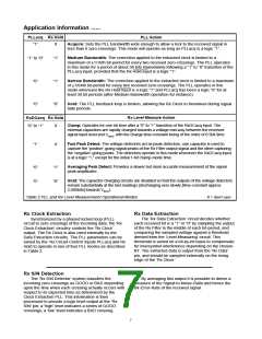
Rx Circuit Control Modes
The operating characteristics of the Rx Level
Measurement and Clock Extraction circuits are
controlled, as shown in Table 2, by logic level inputs
applied to the ‘PLLacq,’ ‘Rx Hold’ and ‘RxDCacq’ pins to
suit a particular application, or to cope with changing
reception conditions.
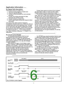
With reference to Figure 5, the Rx Mode Control
diagram: In general, a data transmission will begin with a
preamble of, for example, “1100110011001100,” to allow
the receive modem to establish timing -and level-lock- as
quickly as possible. After the Rx carrier has been
detected, and during the time that the preamble is
expected, the ‘RxDCacq’ and ‘PLLacq’ inputs should be
switched from a logic “0 to 1” so that the Level Measuring
and Clock Extraction modes are operated and
sequenced as shown.
The ‘Rx Hold’ input should normally be held at a logic
“1” while data is being received, but may be driven to a
logic “0” to freeze the Level Measuring and Clock
Extraction circuits during a fade. If the fade lasts for less
than 200 bit periods, normal operation can be resumed
by returning the ‘Rx Hold’ input to a logic “1” at the end of
the fade. For longer fades, it may be better to reset the
Level Measuring circuits by placing the ‘RxDCacq’ to a
logic “1” for 10 to 20 bit periods.
‘Rx Hold’ has no effect on the Level Measuring
circuits while ‘RxDCacq’ is at a logic “1”, and has no
effect on the PLL while ‘PLLacq’ is at a logic “1”.
A logic “0” on ‘Rx Hold’ does not disable the ‘Rx
Clock’ output, and the Rx Data Extraction and S/N
Detector circuits will continue to operate.
DATA
PREAMBLE
Rx SIGNAL
INPUT
Rx CAR DET
(RSSI) INPUT
RxDCacq
Rx LEVEL
MEASURE
MODE
’FAST PEAK
DETECT’
’AVERAGING PEAK
’CLAMP’
DETECT’
PLLacq
CLOCK
EXTRACTION
CCT MODE
30 BITS
’NARROW BW’
’ACQUIRE’
’MEDIUM BW’
Fig.5 Rx Mode Control Diagram
6

 CMLMICRO [ CML MICROCIRCUITS ]