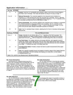
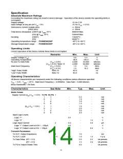
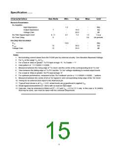
Application Information ......
Radio Channel Requirements
To achieve legal adjacent channel performance at high bit-rates, a radio with an accurate carrier frequency and
an accurate modulation index will be required.
To achieve optimum channel utilization, (eg. low BER and high data-rates) attention must be paid to the phase
and frequency response of both the IF and baseband circuitry.
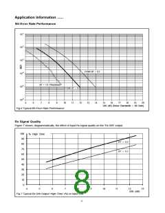
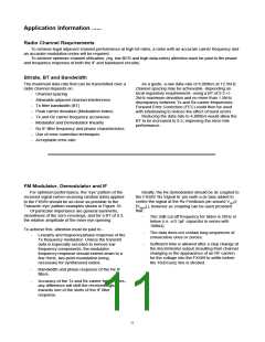
Bitrate, BT and Bandwidth
The maximum data rate that can be transmitted over a
radio channel depends on:
As a guide, a raw data-rate of 8,000b/s at 12.5kHz
channel spacing may be achievable -depending on
local regulatory requirements- using a BT of 0.3 +/-
2kHz maximum deviation and no more than 1.5kHz
discrepancy between Tx and Rx carrier frequencies.
Forward Error Correction (FEC) could then be used
with interleaving to reduce the effect of burst errors.
Reducing the data-rate to 4,800b/s would allow the
BT to be increased to 0.5, improving the error-rate
performance.
- Channel spacing
- Allowable adjacent channel interference
- Tx filter bandwidth (BT)
- Peak carrier deviation (Modulation Index)
- Tx and Rx carrier frequency accuracies
- Modulator and Demodulator linearity
- Rx IF filter frequency and phase characteristics
- Use of error correction techniques
- Acceptable error-rate
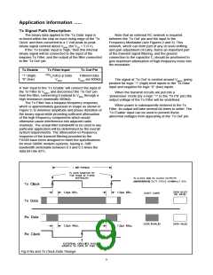
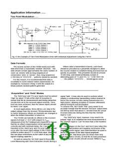
FM Modulator, Demodulator and IF
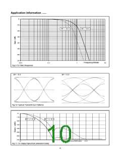
For optimum performance, the ‘eye’ pattern of the
received signal (when receiving random data) applied
to the FX589 should be as close as possible to the
Transmit ‘eye’ pattern examples shown in Figure 10.
Of particular importance are general symmetry,
cleanliness of the zero-crossings, and for a BT of 0.3,
the relative amplitude of the inner eye opening.
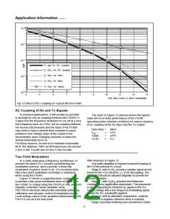
Ideally, the Rx demodulator should be dc coupled to
the FX589 ‘Rx Signal In’ pin (with a dc bias added to
centre the signal at the Rx Feedback pin around VDD/2
[VBIAS] ), however ac coupling can be used provided
that:
-
The 3dB cut-off frequency for 8kb/s is 20Hz or
below (i.e. a 0.1µF capacitor in series with
100kΩ).
To achieve this, attention must be paid to -
-
-
The data does not contain long sequences of
consecutive ones or zeroes.
-
Linearity and frequency/phase response of the
Tx frequency modulator. Unless the transmit
data is especially encoded to remove low
frequency components, the modulator
frequency response should extend down to a
few Hertz, two-point modulation being
necessary for synthesised radios.
Sufficient time is allowed after a step change at
the discriminator output (resulting from channel
changing or the appearance of an RF carrier)
for the voltage into the FX589 to settle before
the ‘RxDCacq’ line is strobed.
-
-
Bandwidth and phase response of the Rx IF
filters.
Accuracy of the Tx and Rx carrier frequencies -
any difference will shift the received signal
towards one of the skirts of the IF filter
response.
11

 CMLMICRO [ CML MICROCIRCUITS ]