Specification ......
Characteristics
See Note
Min.
Typ.
Max.
Unit
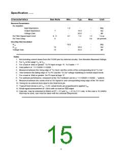
Receive Parameters
Rx Amplifier -
Input Impedance
1.0
-
-
-
MΩ
kΩ
Output Impedance
Voltage Gain
7
-
-
10.0
50.0
1.0
-
-
dB
Rx Filter Signal Input Level
8, 11
9
0.7
-
1.3
3.0
V p-p
bit-periods
Rx Time Delay
On-Chip Xtal Oscillator
R IN
10.0
-
-
-
-
MΩ
kΩ
dB
R OUT
12
12
-
-
50.0
25.0
Voltage Gain
Notes
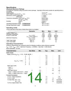
1. Not including current drawn from the FX589 pins by external circuitry. See Absolute Maximum Ratings.
2. For VIN in the range VSS to VDD.
3
For a load of 10kΩ or greater. Tx PS input at logic “0”; Tx Enable = “1”.
4. Data pattern of “1111000011110000 ..”
5. Measured between the rising edge of ‘Tx Clock’ and the centre of the corresponding bit at ‘Tx Out.’
6. Time between the falling edge of ‘Tx PS’ and the ‘Tx Out’ voltage stabilising to normal output levels.
7. For a load of 10kΩ or greater. Rx PS input at logic “0”.
8. For optimum performance, measured at the ‘Rx Feedback’ pin for a “1111000011110000 ...” pattern.
9. Measured between the centre of bit at ‘Rx Signal In’ and corresponding rising edge of the ‘Rx Clock’.
10. Timing for an external clock input to the Xtal/Clock pin.
11. 'Typical' level shown is at VDD = 5.0V; actual levels are proportional to applied VDD.
12. Small signal measurement at 1.0kHz with no load on Xtal output.
13. Data rate may be extended to 80kb/s at BT = 0.5 and VDD = 4.5 to 5.5 V only. In this case a 10.24MHz
Xtal may be used, care must be taken with the external components.
15

 CMLMICRO [ CML MICROCIRCUITS ]