RF Quadrature Transceiver / RF Quadrature Receiver
CMX991/CMX992
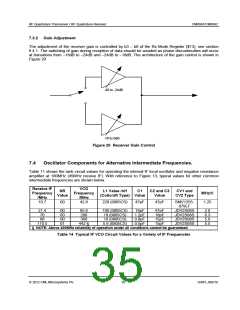
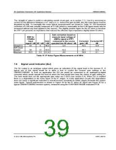
7.3.2 Gain Adjustment
The adjustment of the receiver gain is controlled by b3 – b0 of the Rx Mode Register ($13), see section
6.4.1. The switching of gain during reception of data should be avoided as phase discontinuities will occur
at transitions from –18dB to –24dB and –24dB to –18dB. The architecture of the gain control is shown in
Figure 20.
-48 to -24dB
-18 to 0dB
Figure 20 Receiver Gain Control
7.4
Oscillator Components for Alternative Intermediate Frequencies.
Table 11 shows the tank circuit values for operating the internal IF local oscillator and negative resistance
amplifier at 180MHz (45MHz receive IF). With reference to Figure 13, typical values for other common
intermediate frequencies are shown below.
Receive IF
Frequency
/MHz
VCO
Frequency
/MHz
NR
Value
L1 Value /nH
(Coilcraft Type) Value
C1
C2 and C3
Value
CV1 and
CV2 Type
MHz/V
10.7
00
42.8
220 (0805CS)
47pF
47pF
SMV1255-
079LF
1.25
21.4
70
90
00
00
00
01
85.6
280
360
100 (0805CS)
18 (0805CS)
10 (0805CS)
5.6 (0805CS)
18pF
1.2pF
0.8pF
0.5pF
47pF
18pF
15pF
15pF
JDV2S08S
JDV2S08S
JDV2S08S
JDV2S08S
2.0
6.3
5.9
5.5
110.5
442 §
§ NOTE: Above 400MHz reliability of operation under all conditions cannot be guaranteed.
Table 14 Typical IF VCO Circuit Values for a Variety of IF Frequencies
2012 CML Microsystems Plc
35
D/991_992/18

 CMLMICRO [ CML MICROCIRCUITS ]