RF Quadrature Transceiver / RF Quadrature Receiver
CMX991/CMX992
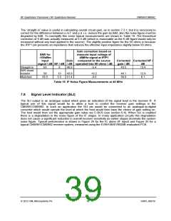
The ‘straight in’ value is useful in calculating overall circuit gain, as in section 7.3.1, but it is necessary to
correct for the difference between e.m.f. and p.d. i.e. reduce the gain by 6dB, also the noise figure must be
degraded by 6dB. To exemplify this some typical measurements are shown in Table 19. The theoretical
correction of 6 dB was actually measured at 5.4 dB (which is reasonable as the 6 dB figure would only be
measured without any load applied to the source). The slightly positive figure for the 50 ohms is because
the IFIP1 pin presents an impedance that reduces the effective input impedance slightly below 50 ohms.
Gain correction based on
SNR for
-100dBm
input
measure input voltage of
45MHz signal at IFIP1
compared to the source
Gain
Corrected Corrected NF /
signal / dB NF / dB / dB operated into 50 ohms / dB
gain / dB
dB
Straight in
50R shunt
resistor
63
8
48.9
-5.4
43.5
13.4
58
65.5
13
5.5
43.9
51.4
+0.2
-0.6
44.1
50.8
12.8
6.1
Matched
Table 19 IF Noise Figure Measurements at 45 MHz
7.8
Signal Level Indicator (SLI)
The SLI output is an analogue output which gives an indication of the signal level in the receiver IF. A
typical use of this signal would be to allow a host to control the receiver gain settings in the
CMX991/CMX992. In such an application the SLI pin would be connected to an analogue-to-digital
converter which would sample the level at which the host would then base the choice of gain setting on.
The host would then set the appropriate gain value via C-BUS (see section 6.4). When SLI is enabled
there is a degradation in the noise figure of the IF stages. In many application circuits this degradation
does not cause a significant reduction in overall receiver sensitivity as earlier stages dominate the system
noise figure. Typical performance is shown in Figure 24 for the IC alone (IF input) and Figure 25 for a
typical CMX991/CMX992 receiver system, measured using the EV9910B/EV9920B evaluation PCB.
2012 CML Microsystems Plc
39
D/991_992/18

 CMLMICRO [ CML MICROCIRCUITS ]