RF Quadrature Transceiver / RF Quadrature Receiver
CMX991/CMX992
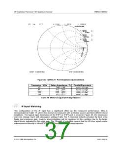
CH1
S
1 U FS
2_: 412.42
-235.34
15.028 pF
45.000 000 MHz
22
1_: 539.72
-96.312
10 MHz
3_: 220.22
-251.82
100 MHz
4_: 131.29
-210.62
150 MHz
2
1
3
4
START 10.000 000 MHz
STOP 150.000 000 MHz
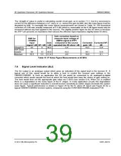
Figure 22 MIXOUT1 Port Impedance (unmatched)
Frequency / MHz
Parallel Equivalent
Series Impedance /
540 – j 96
10
45
100
150
557 // 5.1pF
547 // 3.7pF
508 // 3.6pF
469 // 3.6pF
412 - j 235
220 – j 252
131 – j 211
Table 16 MIXOUT Equivalent Impedances
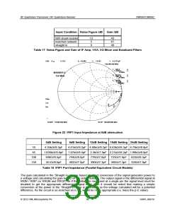
7.7
IF Input Matching
The configuration of the IF input has a significant effect on the measured performance. This is
demonstrated in Table 17, where the receiver is measured with a 50 ohm source and three different input
conditions. The typical input impedance of the IFIP1 or IFIP2 port is shown in Figure 23, the impedance
does not change much with attenuation setting (Table 18). A matched network provides the best noise
figure and maximum gain, however intermodulation will be degraded in this condition due to the larger
signal levels indicated by the extra gain. The ‘Straight in’ condition means that the 50 ohm signal source
was connected directly to either IFIP1 or IFIP2 input via a dc blocking capacitor.
2012 CML Microsystems Plc
37
D/991_992/18

 CMLMICRO [ CML MICROCIRCUITS ]