RF Quadrature Transceiver / RF Quadrature Receiver
CMX991/CMX992
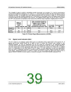
Input Condition Noise Figure /dB Gain /dB
50R shunt resistor
matched network
straight in
13
5
8
43
61
49
Table 17 Noise Figure and Gain of IF Amp, VGA, I/Q Mixer and Baseband Filters
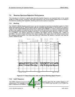
CH2
S
1 U FS
4_: 43.684
-115.87
9.1573 pF
150.000 000 MHz
11
1_: 582.5
-1.4823 k
10 MHz
MARKER 4
150 MHz
2_: 82.813
-380.78
45 MHz
3_: 50.047
-172.98
100 MHz
1
PRm
Cor
Del
2
4
3
START 10.000 000 MHz
STOP 150.000 000 MHz
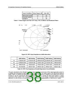
Figure 23 IFIP1 Input Impedance at 0dB attenuation
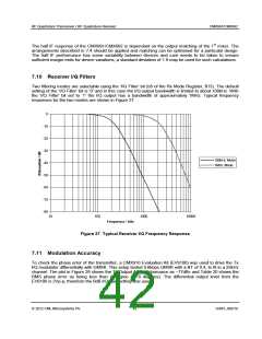
Freq (MHz)
0dB Setting
6dB Setting
12dB Setting 18dB Setting 24dB Setting
10
45
4.35k//9.3pF
1.836k//8.9pF
648//8.5pF
4.61k//9.2pF 4.80k//8.2pF 6.63k//8.3pF 4.75k//8.8pF
1.97k//8.4pF 2.3k//7.9pF 2.21k//8.2pF 1.96k//8.8pF
100
150
744//8.0pF
402//7.6pF
776//7.6pF
390//7.3pF
723//7.8pF
365//7.3pF
633//8.3pF
326//7.8pF
351//8.0pF
Table 18 IFIP1 Port Impedance (Parallel Equivalent Circuit Models)
The gain calculated in the ‘Straight in’ case is based on direct conversion of the signal generator power to
a voltage and calculating the gain based on the output voltage. The output signal is the differential signal at
RXIN / RXIP (or RXQN and RXQP) so if the voltage is measured at a single pin the signal level must be
doubled to get the appropriate differential signal level. Also it should be noted that making a simple
conversion of the power in the ‘Straight in’ case is erroneous as the voltage calculated will be a potential
difference. As the circuit is un-matched an e.m.f. would be more appropriate (i.e. twice the p.d. value).
2012 CML Microsystems Plc
38
D/991_992/18

 CMLMICRO [ CML MICROCIRCUITS ]