RF Quadrature Transceiver / RF Quadrature Receiver
CMX991/CMX992
7
Application Notes
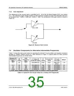
7.1
General
The CMX991/CMX992 chips are RF systems designed for digital wireless applications. These devices
address the needs of various data systems, both product standards and regulatory requirements, including
TETRA (EN 300 392-2, EN 300 394-1, EN 302 561) and DMR (EN 300 113). APCO Project 25 (TIA-
102.CAAB).
7.2
Using the CMX992 with the CMX998
The CMX998 device linearises an external RF PA and is an ideal complement to the CMX992.
To simplify CMX992+CMX998 designs the CMX992 uses the same physical interface architecture as the
CMX998 (SDI is equivalent to CDATA, SDO to RDATA). The C-BUS registers of the two devices are also
compatible and allow the CMX992 and CMX998 to be connected to the same C-BUS interface pins,
including Chip Select (CSN), assuming the drive capabilities of the host are adequate.
7.3
Receiver Gain Issues
7.3.1 Typical Gain Distribution
The detailed design of a receiver for any particular application will vary. The gain of the receiver depends
on the matching arrangements and impedances. A typical design partition is shown in Table 13 based on
the EV9910B / EV9920B Evaluation PCB. Thus if a –60dBm signal is presented to the input with the
matching arrangements in Figure 6 (mixer) and Figure 7 (IF filter matching), the signal at each I and Q
channel output should be ~712mVp-p differential or ~356mVp-p on each of the differential output pins
RXIN, RXIP, RXQP and RXQN. Note that the gain of IF matching and filtering must be carefully modelled:
it is necessary to consider the complex matching impedances of the mixer output pins and the IF input
pins (see sections 7.6 and 7.7). Also note that normal production tolerances will result in gain variations.
Input
-60
50
Filt+LNA Attenuator Match #1
Mixer
-41.5
400
Match #2
Filter
Match #3 IF Stages
Power
Impedance
Voltage (rms)
V (p-p)
Output Voltage pin RXIP (p-p)
Stage Gain
-60
50
-44
50
-51
50
-51.5
300
dBm
ohms
V
V
mV
dB
220
650
1.59E-03
4.49E-03
1200
0.252
0.712
356
2.24E-04 2.24E-04 1.41E-03 6.30E-04 1.46E-03 5.32E-03
6.32E-04 6.32E-04 3.99E-03 1.78E-03 4.12E-03 1.51E-02
0
0
16
16
-7
-7
-0.5
7.28
10
11.25
44
44
Stage Voltage Gain
-10.5
dB
Mixer Voltage Gain
18.5 dBV/V
Total Gain
61.0 dB
Table 13 Typical Receiver Gain Partitioning
Notes:
1) Mixer input loss based on TC1-1-13M+ at 500MHz
2) ‘Mixer’ is CMX991 / CMX992 mixer; ‘IF Stages’ is CMX991 / CMX992 IF and I/Q demodulator stages
between IFIN1 / IFIN2 and RXIN, RXIP, RXQP and RXQN.
2012 CML Microsystems Plc
34
D/991_992/18

 CMLMICRO [ CML MICROCIRCUITS ]