CS5525 CS5526
Ω
10
+5V
Analog
Supply
µ
µ
F
0.1
F
0.1
2
13
VD+
VA+
500kΩ
10
9
XOUT
20
p
20
F
VREF+
19
VREF-
AIN+
30mV
F.S.
32.768 ~ 100kHz
Optional
-
+
3
XIN
CS5525
CS5526
Clock
Source
18
CS
4
11
AIN-
AGND
A3
Serial
Data
SCLK
1
16
15
7
17
14
SDI
Interface
A2
A1
A0
SDO
6
NBV CPD DGND
5
8
12
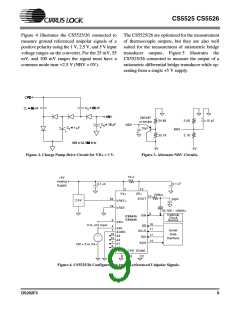
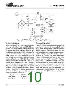
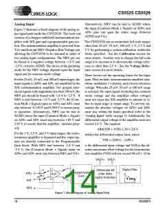
Figure 5. CS5525/26 Configured for Single Supply Bridge Measurement.
System Initialization
Command Operation
When power to the CS5525/26 is applied, they are
held in a reset condition until their 32.768 kHz os-
cillators have started and their start-up counter-tim-
er elapses. Due to the high Q of a 32.768 kHz
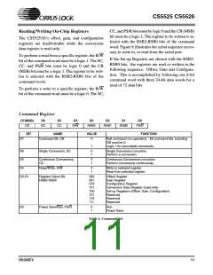
The CS5525/26 include a microcontroller with five
registers used to control the converter. Each regis-
ter is 24-bits in length except the 8-bit command
register (command, configuration, offset, gain, and
crystal, the oscillators take 400-600 ms to start. The conversion data). After a system initialization or re-
converter’s counter-timer counts no more than set, the serial port is initialized to the command
1024 oscillator clock cycles to make sure the oscil- mode and the converter stays in this mode until a
lator is fully stable. During this time-out period the valid 8-bit command is received (the first 8-bits
serial port logic is reset and the RV (Reset Valid) into the serial port). Table 1 lists all the valid com-
bit in the configuration register is set. A reset can be mands. Once a valid 8-bit command (a read or a
initiated at any time by writing a logic 1 to the RS
(Reset System) bit in the configuration register.
write command word) is received and interpreted
by the command register, the serial port enters the
This automatically sets the RV bit until the RS bit data mode. In data mode the next 24 serial clock
is written to logic 0, and the configuration register pulses shift data either into or out of the serial port
is read. After a reset, the on-chip registers are ini- (72 serial clock pulses are needed if set-up register
tialized to the following states and the converters
are ready to perform conversions.
is selected). See Table 2 for configuring the
CS5525/26.
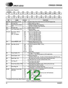
configuration register: 000040(H)
offset register:
gain register:
000000(H)
800000(H)
10
DS202F3

 CIRRUS [ CIRRUS LOGIC ]