CS5525 CS5526
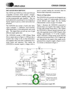
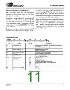
Figure 4 illustrates the CS5525/26 connected to The CS5525/26 are optimized for the measurement
measure ground referenced unipolar signals of a
positive polarity using the 1 V, 2.5 V, and 5 V input
of thermocouple outputs, but they are also well
suited for the measurement of ratiometric bridge
voltage ranges on the converter. For the 25 mV, 55 transducer outputs. Figure 5 illustrates the
mV, and 100 mV ranges the signal must have a CS5525/26 connected to measure the output of a
common mode near +2.5 V (NBV = 0V).
ratiometric differential bridge transducer while op-
erating from a single +5 V supply.
2N 5087
or similar
+
34.8K
30.1K
2.0K
2.1K
10 µF
N BV
10µF
N BV
+
-5V
-5V
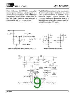
Figure 2. Charge Pump Drive Circuit for VD+ = 3 V.
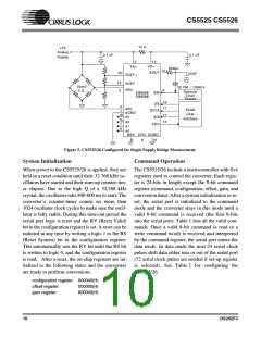
Figure 3. Alternate NBV Circuits.
Ω
10
+5V
Analog
µ
µ
0.1
F
0.1
F
Supply
2
13
VD+
XOUT
VA+
VREF+
VREF-
500kΩ
10
9
p
20
19
20
F
2.5V
32.768 ~ 100kHz
Optional
XIN
C S5525
CS5526
Clock
3
Source
AIN+
18
0 to +5V Input
CS
4
1
AIN-
AGND
A3
11
Serial
Data
SCLK
16
17
14
+
-
SDI
Interface
15
7
A2
A1
A0
SDO
CM = 0 to VA+
6
NBV CPD DGND
5
8
12
Figure 4. CS5525/26 Configured for ground-referenced Unipolar Signals.
DS202F3
9

 CIRRUS [ CIRRUS LOGIC ]