CS3310
to prevent “clicks and pops” which occur with gain
changes if an appreciable offset is present.
ter and the volume control register to zero and per-
forms an offset calibration. The device should
remain muted until the supply voltages have settled
to ensure an accurate calibration. The device also
includes an internal power-on reset circuit that re-
quires approximately 100 µs to settle and will ig-
nore any attempts to address the internal registers
during this period.
Source Impedance Requirements
The CS3310 requires a low source impedance to
achieve maximum performance. The ESD protec-
tion diodes on the analog input pins are reversed bi-
ased during normal operation. A characteristic of a
reversed biased diode is a non-linear voltage de-
pendent capacitance which can be a source of dis-
tortion if the source impedance becomes
appreciable relative to the reversed biased diode
capacitance. Source impedances equal to or less
than 600 ohms will avoid this distortion mecha-
nism for the CS3310.
The offset calibration minimizes internally gener-
ated offsets and ignores offsets applied to the AIN
pins. External clocks are not required for calibra-
tion.
Although the device is tolerant to power supply
variation, the device will enter a hardware mute
state if the power supply voltage drops below ap-
proximately ±3.5 volts. A power-up sequence will
be initiated if the power supply voltage returns to
greater than ±3.5 volts.
Mute
Muting can be achieved by either hardware or soft-
ware control. Hardware muting is accomplished
via the MUTE input and software muting by load-
ing all zeroes into the volume control register.
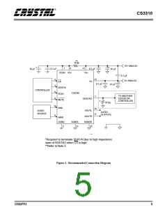
Applying power to VD+ prior to VA+ creates a
SCR latch-up condition. Refer to Figure 2 for the
recommended power connections.
MUTE disconnects the internal buffer amplifiers
from the output pins and terminates AOUTL and
AOUTR with 10 kΩ resistors to ground. The mute
is activated with a zero crossing detection (inde-
pendent of the zero cross enable status) or an 18 ms
timeout to eliminate any audible “clicks” or
“pops”. MUTE also initiates an internal offset cal-
ibration.
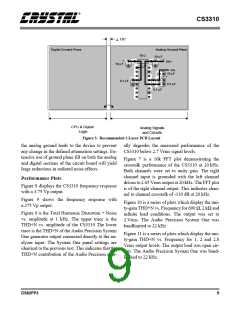
PCB Layout, Grounding and Power Supply
Decoupling
As with any high performance device which con-
tains both analog and digital circuitry, careful at-
tention to power supply and grounding
arrangements must be observed to optimize perfor-
mance. Figure 2 shows the recommended power
arrangements with VA+ connected to a clean +5
volt supply and VA- connected to a clean -5 volt
supply. VD+ powers the digital interface circuitry
and should be powered from VA+, as shown in Fig-
ure 2, to avoid potentially destructive SCR latch-
up. Decoupling capacitors should be located as
near to the CS3310 as possible, see Figure 5.
A software mute is implemented by loading all ze-
roes into the volume control register. The internal
amplifier is set to unity gain with the amplifier in-
put connected to the maximum attenuation point of
the resistive divider, AGND.
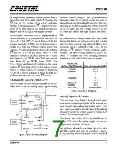
A “soft mute” can be accomplished by sequentially
ramping down from the current volume control set-
ting to the maximum attenuation code of all zeroes.
The printed circuit board layout should have sepa-
rate analog and digital regions with individual
ground planes. The CS3310 should reside in the an-
alog region as shown in Figure 5. Care should be
taken to ensure that there is minimal resistance in
Power-Up Considerations
Upon initial application of power, the MUTE pin of
the CS3310 should be set low to initiate a power-up
sequence. This sequence sets the serial shift regis-
8
DS82PP3

 CIRRUS [ CIRRUS LOGIC ]