CS3310
GENERAL DESCRIPTION
Serial Data Interface
The CS3310 is a stereo, digital volume control de- The CS3310 has a simple, three wire interface that
signed for audio systems. The levels of the left and
right analog input channels are set by a 16-bit serial
consists of three input pins: SDATAI, serial data
input; SCLK, serial data clock and CS, the chip se-
data word; the first 8 bits address the right channel lect input. SDATAO, serial data output, enables the
and the remaining 8 bits address the left channel, as
detailed in Table 1. Resistor values are decoded to
0.5 dB resolution by an internal multiplexer for a
total attenuation range of -95.5 dB. An output am-
plifier stage provides a programmable gain of up to
31.5 dB in 0.5 dB steps. This results in an overall 8-
bit adjustable range of 127 dB.
user to read the current volume setting or provide
daisy-chaining of multiple CS3310’s.
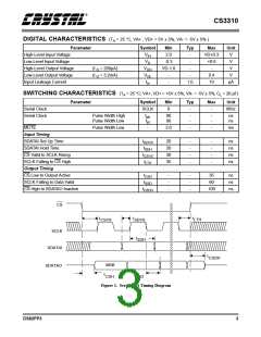
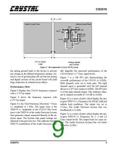
The 16-bit serial data is formatted MSB first and
clocked into SDATAI by the rising edge of SCLK
with CS low as shown in Figure 3. The data is
latched by the rising edge of CS and the analog out-
put levels of both left and right channels are set.
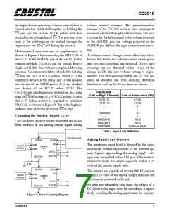
The CS3310 operates from ±5 V supplies and ac- The existing data in the volume control data regis-
cepts inputs up to ±3.75 V. Once in operation, the
CS3310 can be brought to a muted state with the
ter is clocked out SDATAO on the falling edge of
SCLK. This data can be used to read current
mute pin, MUTE, or by writing all zeros to the vol- gain/attenuation levels or to daisy chain multiple
ume control registers. The device contains a simple CS3310’s. See Figure 1 for proper setup and hold
three wire serial interface which accepts 16-bit da- times for CS, SDATAI, SCLK, and SDATAO.
ta. This interface also supports daisy-chaining ca-
pability.
SCLK and SDATAI should be active only during
volume setting operations to achieve optimum dy-
namic range.
SYSTEM DESIGN
Daisy Chaining
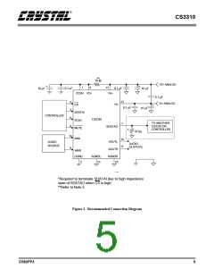
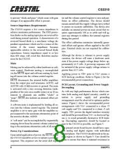
Very few external components are required to sup-
port the CS3310. Normal power supply decoupling Digitally controlled, multi-channel audio systems
components are all that is required, as shown in often result in complex address decoding which
Figure 2.
complicates PCB layout. This is greatly simplified
with the daisy-chaining capability of the CS3310.
CS
SCLK
SDATAI
R7 R6 R5 R4 R3 R2 R1 R0 L7 L6 L5 L4 L3 L2 L1 L0
SDATAO
R7 R6 R5 R4 R3 R2 R1 R0 L7 L6 L5 L4 L3 L2 L1 L0
L0 = Left Channel Least Significant Bit
L7 = Left Channel Most Significant Bit
R0 = Right Channel Least Significant Bit
R7 = Right Channel Most Significant Bit
SDATAI is latched internally on the rising edge of SCLK
SDATAO transitions after the falling edge of SCLK
SDATAO bits reflect the data previously loaded into the CS3310
Figure 3. Serial Port Timing
6
DS82PP3

 CIRRUS [ CIRRUS LOGIC ]