CS3310
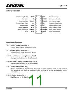
PIN DESCRIPTION
1
16
15
14
13
12
11
Zero Crossing Enable
ZCEN
CS
AINL
Left Channel Input
Left Analog Ground
Left Channel Output
2
Chip Select
Serial Data Input
AGNDL
AOUTL
VA-
3
4
5
6
7
8
SDATAI
VD+
Positive Digital Power
Digital Ground
Negative Analog Power
Positive Analog Power
Right Channel Output
Right Analog Ground
Right Channel Input
DGND
SCLK
VA+
Serial Clock Input
AOUTR
Serial Data Output SDATAO
Mute MUTE
10 AGNDR
AINR
9
Power Supply Connections
VA+ - Positive Analog Power, Pin 12.
Positive analog supply. Nominally +5 volts.
VA- - Negative Analog Power, Pin 13.
Negative analog supply. Nominally -5 volts.
AGNDL - Left Channel Analog Ground, Pin 15.
Analog ground reference for the left channel.
AGNDR - Right Channel Analog Ground, Pin 10.
Analog ground reference for the right channel.
VD+ - Positive Digital Power, Pin 4.
Positive supply for the digital section. Nominally +5 volts. Applying power to VD+ prior to
VA+ creates a SCR latch-up condition. Refer to Figure 2 for the recommended power
connections.
DGND - Digital Ground, Pin 5.
Digital ground for the digital section.
DS82PP3
11

 CIRRUS [ CIRRUS LOGIC ]