CS3310
Analog Inputs and Outputs
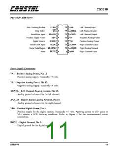
AINL, AINR - Left and Right Channel Analog Inputs, Pins 16, 9.
Analog input connections for the left and right channels. Nominally ±3.75 volts for a full scale
input.
AOUTL, AOUTR - Left and Right Channel Analog Outputs, Pins 14, 11.
Analog outputs for the left and right channels. Nominally ±3.75 volts for a full scale output.
Digital Pins
SDATAI - Serial Data Input, Pin 3.
Serial input data that sets the analog output level of the left and right channels. The data is
formatted in a 16-bit word. The first eight bits clocked into this pin control the analog output
level for the right channel, and the second eight bits clocked into the device control the analog
output level for the left channel. The data is clocked into the CS3310 by the rising edge of
SCLK.
SDATAO - Serial Data Output, Pin 7.
Serial output data that provides daisy-chaining of multiple CS3310’s. This serial output will
output the previous sixteen bits of volume control data that were clocked into the SDATAI pin.
SDATAO will enter a High Impedance State when CS is High.
SCLK - Serial Input Clock, Pin 6.
Serial clock that clocks in the individual bits of serial data from the SDATAI pin. This clock is
also used to clock out the individual bits from the SDATAO pin. The SDATAI data is latched
on the rising edge, and SDATAO data is clocked out on the falling edge.
CS - Chip Select, Pin 2.
When high, the SDATAO output is held in a high impedance state. A falling transition defines
the start of the 16-bit volume control word into the device. The 16-bit input data is latched into
the control register on the rising edge of CS.
MUTE - Mute, Pin 8.
Forces both the left and right analog output channels to ground. An offset calibration is
initiated following the low transition of MUTE. Calibration requires a minimum mute period of
2 ms.
ZCEN - Zero Crossing Enable, Pin 1.
This pin enables or disables the zero crossing detection and time-out function used during
analog output level transitions. A high level on this pin enables the zero crossing detection
function. A low level on this pin disables the zero crossing detection.
12
DS82PP3

 CIRRUS [ CIRRUS LOGIC ]