CS4365
set to -3.0 dB. This same volume control register affects PCM output levels. There is no need to change the vol-
ume control setting between PCM and DSD in order to have the 0dB output levels match (both 0 dBFS and 0 dB-
SACD will output at -3 dB in this case).
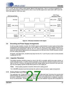
DSD Phase
DSD Normal Mode
Modulation Mode
BCKA
(128Fs)
Not Used
DSD_SCLK
DSD_SCLK
BCKA
(64Fs)
BCKD
(64Fs)
DSD_SCLK
Not Used
DSDAx,
DSDBx
D0
D0
D1
D2
D2
D1
DSDAx,
DSDBx
Not Used
D1
Figure 20. DSD phase modulation mode diagram
3.9
Grounding and Power Supply Arrangements
As with any high resolution converter, the CS4365 requires careful attention to power supply and grounding
arrangements if its potential performance is to be realized. The Typical Connection Diagram shows the rec-
ommended power arrangements, with VA, VD, VLC, and VLS connected to clean supplies. If the ground
planes are split between digital ground and analog ground, the GND pins of the CS4365 should be connect-
ed to the analog ground plane.
All signals, especially clocks, should be kept away from the FILT+ and VQ pins in order to avoid unwanted
coupling into the DAC.
3.9.1 Capacitor Placement
Decoupling capacitors should be placed as close to the DAC as possible, with the low value ceramic ca-
pacitor being the closest. To further minimize impedance, these capacitors should be located on the same
layer as the DAC. If desired, all supply pins with similar voltage ratings may be connected to the same sup-
ply, but a decoupling capacitor should still be placed on each supply pin.
Notes: All decoupling capacitors should be referenced to analog ground.
The CDB4365 evaluation board demonstrates the optimum layout and power supply arrangements.
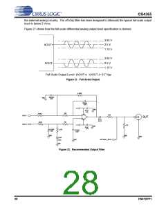
3.10 Analog Output and Filtering
The application note “Design Notes for a 2-Pole Filter with Differential Input” discusses the second-order
Butterworth filter and differential to single-ended converter which was implemented on the CS4365 evalua-
tion board, CDB4365, as seen in Figure 22. The CS4365 does not include phase or amplitude compensa-
tion for an external filter. Therefore, the DAC system phase and amplitude response will be dependent on
DS670PP1
27

 CIRRUS [ CIRRUS LOGIC ]