CS4365
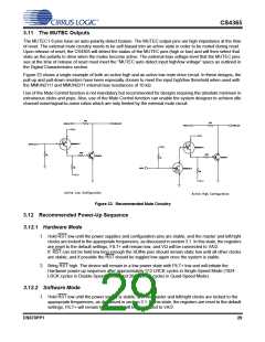
2. Bring RST high. The device will remain in a low power state with FILT+ low for 512 LRCK cycles in
Single-Speed Mode (1024 LRCK cycles in Double-Speed Mode, and 2048 LRCK cycles in Quad-
Speed Mode).
3. In order to reduce the chances of clicks and pops, perform a write to the CP_EN bit prior to the
completion of approximately 512 LRCK cycles in Single-Speed Mode (1024 LRCK cycles in Double-
Speed Mode, and 2048 LRCK cycles in Quad-Speed Mode). The desired register settings can be
loaded while keeping the PDN bit set to 1. Set the RMP_UP and RMP_DN bits to 1, then set the format
and mode control bits to the desired settings.
If more than the stated number of LRCK cycles passes before CPEN bit is written then the chip will
enter Hardware mode and begin to operate with the M0-M4 as the mode settings. CPEN bit may be
written at anytime, even after the Hardware sequence has begun. It is advised that if the CPEN bit can
not be set in time then the SDINx pins should remain static low (this way no audio data can be
converted incorrectly by the hardware mode settings).
4. Set the PDN bit to 0. This will initiate the power-up sequence, which lasts approximately 50 µs.
3.13 Recommended Procedure for Switching Operational Modes
For systems where the absolute minimum in clicks and pops is required, it is recommended that the MUTE
bits are set prior to changing significant DAC functions (such as changing sample rates or clock sources).
The mute bits may then be released after clocks have settled and the proper modes have been set.
It is required to have the device held in reset if the minimum high/low time specs of MCLK can not be met
during clock source changes.
3.14 Control Port Interface
The control port is used to load all the internal register settings in order to operate in software mode (see
the “Parameter Definitions” on page 45). The operation of the control port may be completely asynchronous
with the audio sample rate. However, to avoid potential interference problems, the control port pins should
remain static if no operation is required.
2
The control port operates in one of two modes: I C or SPI.
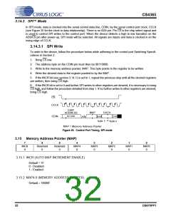
3.14.1 MAP Auto Increment
The device has MAP (memory address pointer) auto increment capability enabled by the INCR bit (also the
2
MSB) of the MAP. If INCR is set to 0, MAP will stay constant for successive I C writes or reads and SPI
writes. If INCR is set to 1, MAP will auto increment after each byte is written, allowing block reads or writes
of successive registers.
2
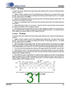
3.14.2 I C Mode
2
In the I C mode, data is clocked into and out of the bi-directional serial control data line, SDA, by the serial
control port clock, SCL (see Figure 24 for the clock to data relationship). There is no CS pin. Pin AD0 en-
ables the user to alter the chip address (001100[AD0][R/W]) and should be tied to VLC or GND as required,
before powering up the device. If the device ever detects a high to low transition on the AD0/CS pin after
power-up, SPI mode will be selected.
30
DS670PP1

 CIRRUS [ CIRRUS LOGIC ]