CM6802
NO BLEED RESISTOR GREEN MODE PFC/PWM CONTROLLER COMBO
PWM Section
PWM Current Limit
Pulse Width Modulator
The DC ILIMIT pin is a direct input to the cycle-by-cycle current
limiter for the PWM section. Should the input voltage at this
pin ever exceed 1V, the output flip-flop is reset by the clock
pulse at the start of the next PWM power cycle. Beside, the
cycle-by-cycle current, when the DC ILIMIT triggered the
cycle-by-cycle current, it also softly discharge the voltage of
soft start capacitor. It will limit PWM duty cycle mode.
Therefore, the power dissipation will be reduced during the
dead short condition.
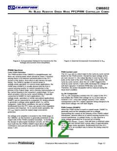
The PWM section of the CM6802 is straightforward, but
there are several points which should be noted. Foremost
among these is its inherent synchronization to the PFC
section of the device, from which it also derives its basic
timing. The PWM is capable of current-mode or
voltage-mode operation. In current-mode applications, the
PWM ramp (RAMP2) is usually derived directly from a
current sensing resistor or current transformer in the
primary of the output stage, and is thereby representative of
the current flowing in the converter’s output stage. DCILIMIT
which provides cycle-by-cycle current limiting, is typically
connected to RAMP2 in such applications. For
,
VIN OK Comparator
The VIN OK comparator monitors the DC output of the PFC
and inhibits the PWM if this voltage on VFB is less than its
nominal 2.45V. Once this voltage reaches 2.45V, which
corresponds to the PFC output capacitor being charged to its
rated boost voltage, the soft-start begins.
voltage-mode, operation or certain specialized applications,
RAMP2 can be connected to a separate RC timing network
to generate a voltage ramp against which VDC will be
compared. Under these conditions, the use of voltage
feedforward from the PFC buss can assist in line regulation
accuracy and response. As in current mode operation, the
DC ILIMIT input is used for output stage overcurrent
protection.
PWM Control (RAMP2)
When the PWM section is used in current mode, RAMP2 is
generally used as the sampling point for a voltage
representing the current on the primary of the PWM’s output
transformer, derived either by a current sensing resistor or a
current transformer. In voltage mode, it is the input for a
ramp voltage generated by a second set of timing
components (RRAMP2, CRAMP2), that will have a minimum value
of zero volts and should have a peak value of approximately
5V. In voltage mode operation, feedforward from the PFC
output buss is an excellent way to derive the timing ramp for
the PWM stage.
No voltage error amplifier is included in the PWM stage of
the CM6802, as this function is generally performed on the
output side of the PWM’s isolation boundary. To facilitate
the design of optocoupler feedback circuitry, an offset has
been built into the PWM’s RAMP2 input which allows VDC to
command a zero percent duty cycle for input voltages
below 1.25V.
2003/06/25 Preliminary
Champion Microelectronic Corporation
Page 12

 CHAMP [ CHAMPION MICROELECTRONIC CORP. ]