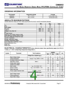
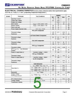
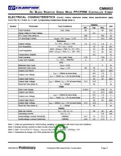
CM6802
NO BLEED RESISTOR GREEN MODE PFC/PWM CONTROLLER COMBO
Functional Description
Green Mode Function
Both PFC Green Mode and PWM Green Mode can be set
separately by selecting proper external value of the external
components. These 2 external components are CT on the
pin 7, RAMP1 pin and the filter resistor at pin 3, ISENSE pin.
The CM6802 consists of an average current controlled,
continuous boost Power Factor Correction (PFC) front end
and a synchronized Pulse Width Modulator (PWM) back
end. The PWM can be used in either current or voltage
mode. In voltage mode, feedforward from the PFC output
buss can be used to improve the PWM’s line regulation. In
either mode, the PWM stage uses conventional trailing
edge duty cycle modulation, while the PFC uses leading
edge modulation. This patented leading/trailing edge
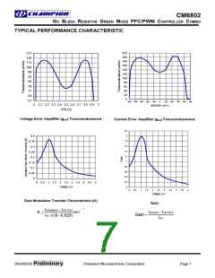
modulation technique results in a higher usable PFC error
amplifier bandwidth, and can significantly reduce the size of
the PFC DC buss capacitor.
Both Blue Angel and Energy Star spec. can be easily met
without shutting off PFC because in CM6802, both PFC and
PWM can set the green mode thresholds. Once the green
mode threshold is triggered, the section will go to pulse
skipping mode.
To Disable PFC Green Mode, a 1 Mega ohm resistor is
needed between IEAO(pin1) and VREF(pin14).
The synchronized of the PWM with the PFC simplifies the
PWM compensation due to the controlled ripple on the PFC
output capacitor (the PWM input capacitor). The PWM
section of the CM6802 runs at the same frequency as the
PFC.
PFC Green Mode Threshold
During the light load, VEAO voltage will reduce. When VEAO
is less than 0.5V, It will turn off PFC. It has 0.25V hysteresis.
If the light load condition continues, the PFC section will stay
at pulse skipping condition without audible noise since the
input power is minimal because VEAO is around 0.75V.
In addition to power factor correction, a number of
protection features have been built into the CM6802. These
include soft-start, PFC overvoltage protection, peak current
limiting, brownout protection, duty cycle limiting, and
under-voltage lockout.
PFC Green Mode Threshold is set by selecting proper Rs
which is the resistor of the RC filter at Isense pin. Its typical
value is from 30 ohm to 300 ohm. If the Rs value is below
30 ohm, and if a 1 Mega ohm resistor is needed between
IEAO(pin1) and VREF(pin14), PFC will not pulse skipping.
During the pulse skipping, the reading of the power meter
can not be trust. It will need to integrate the real power than
average it with the time to get the average power.
To further reduce the power and improve the light load
efficiency, the values of resistor dividers at VFB and VRMS
need to be doubled or tripled. However, it will increase the
layout sensitivity.
Oscillator (RAMP1)
The oscillator frequency is determined by the values of RT
and CT, which determine the ramp and off-time of the
oscillator output clock:
1
fOSC
=
which is the internal clock
tRAMP + tDEADTIME
frequency, fosc=2 x fpwm= 4 x fpfc
The Clock period of the oscillator is derived from the
following equation:
To Disable PFC Green Mode, a 1 Mega ohm resistor is
needed between IEAO(pin1) and VREF(pin14).
V
REF −1.25
REF − 3.75
tRAMP = CT x RT x In
at VREF = 7.5V:
PWM Green Mode Threshold
V
During the light load, PWM section duty cycle also reduces.
When the PWM section duty cycle is less than the internal
clock duty cycle which is set by the CT at RAMP1, pin 7, the
PWM section will start pulse skipping. By selecting the
proper CT, user can program the PWM Green Mode
Threshold. Usually, CT is 1nF.
tRAMP = CT x RT x 0.51
The dead time of the oscillator may be determined using:
2.5V
tDEADTIME
=
x CT = 450 x CT
5.5mA
Power Factor Correction
EXAMPLE:
Power factor correction makes a nonlinear load look like a
resistive load to the AC line. For a resistor, the current drawn
from the line is in phase with and proportional to the line
voltage, so the power factor is unity (one). A common class
of nonlinear load is the input of most power supplies, which
use a bridge rectifier and capacitive input filter fed from the
line. The peak-charging effect, which occurs on the input
filter capacitor in these supplies, causes brief high-amplitude
pulses of current to flow from the power line, rather than a
sinusoidal current in phase with the line voltage.
For the application circuit shown in the datasheet, with the
oscillator running at:
1
f
OSC = 280kHz =
= 2 x fpwm = 4 x fpfc. Here, fpwm
t
RAMP
=140KHz and fpfc=70KHz.
Selecting standard components values, CT = 1.0nF, and RT
= 5.0kΩ
2003/06/25 Preliminary
Champion Microelectronic Corporation
Page 8

 CHAMP [ CHAMPION MICROELECTRONIC CORP. ]