CAT5419
four Data Registers and the associated Wiper Control
Register. Any data changes in one of the Data Registers
is a non-volatile operation and will take a maximum of
5ms.
WIPER CONTROL AND DATA REGISTERS
Wiper Control Register (WCR)
TheCAT5419containstwo6-bitWiperControlRegisters,
one for each potentiometer. The Wiper Control Register
output is decoded to select one of 64 switches along its
resistor array. The contents of the WCR can be altered
in four ways: it may be written by the host via Write Wiper
Control Register instruction; it may be written by
transferring the contents of one of four associated Data
RegistersviatheXFRDataRegisterinstruction,itcanbe
modified one step at a time by the Increment/decrement
instruction (see Instruction section for more details).
Finally, it is loaded with the content of its data register
zero (DR0) upon power-up.
If the application does not require storage of multiple
settingsforthepotentiometer,theDataRegisterscanbe
used as standard memory locations for system
parameters or user preference data.
INSTRUCTIONS
Four of the nine instructions are three bytes in length.
These instructions are:
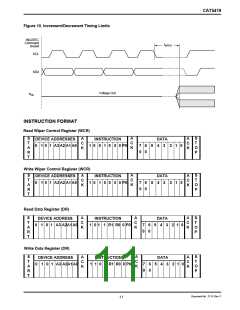
— Read Wiper Control Register - read the current
wiperpositionoftheselectedpotentiometerintheWCR
— Write Wiper Control Register - change current
The Wiper Control Register is a volatile register that
loses its contents when the CAT5419 is powered-down.
Although the register is automatically loaded with the
value in DR0 upon power-up, this may be different from
the value present at power-down.
wiperpositionintheWCRoftheselectedpotentiometer
— Read Data Register - read the contents of the
selected Data Register
— Write Data Register - write a new value to the
Data Registers (DR)
selected Data Register
Each potentiometer has four 6-bit non-volatile Data
Registers. These can be read or written directly by the
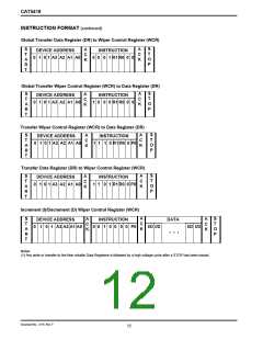
host. Data can also be transferred between any of the
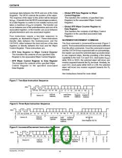
The basic sequence of the three byte instructions is
illustrated in Figure 8. These three-byte instructions
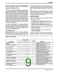
Table 3. Instruction Set
Instruction Set
WCR0/
P0
0
0
Instruction
I3
I2
I1
I0
R1
R0
Operation
Read Wiper Control
Register
1
0
0
1
0
0
1/0
Read the contents of the Wiper Control
Register pointed to by P0
Write Wiper Control Register
1
1
1
1
0
0
1
1
1
1
0
0
0
1
0
1
0
0
0
0
0
0
1/0
1/0
1/0
1/0
Write new value to the Wiper Control
Register pointed to by P0
Read Data Register
1/0 1/0
1/0 1/0
1/0 1/0
Read the contents of the Data Register
pointed to by P0 and R1-R0
Write Data Register
Write new value to the Data Register
pointed to by P0 and R1-R0
XFR Data Register to Wiper
Control Register
Transfer the contents of the Data Register
pointed to by P0 and R1-R0 to its
associated Wiper Control Register
XFR Wiper Control Register
to Data Register
1
0
1
0
1
0
0
0
1
0
0
1
0
1
0
0
1/0 1/0
1/0 1/0
1/0 1/0
0
0
0
0
1/0
0
Transfer the contents of the Wiper Control
Register pointed to by P0 to the Data
Register pointed to by R1-R0
Gang XFR Data Registers
to Wiper Control Registers
Transfer the contents of the Data Registers
pointed to by R1-R0 of both pots to their
respective Wiper Control Register
Gang XFR Wiper Control
Registers to Data Register
0
Transfer the contents of both Wiper Control
Registers to their respective data Registers
pointed to by R1-R0 of both pots
Increment/Decrement Wiper
Control Register
0
0
1/0
Enable Increment/decrement of the Control
Latch pointed to by P0
Note: 1/0 = data is one or zero
Document No. 2115, Rev. F
9

 CATALYST [ CATALYST SEMICONDUCTOR ]