COMMUNICATIONS WITH THE XTR108 USING A
MICROCONTROLLER
SCLK is driven low by the
microcontroller just before
CS1 is driven low.
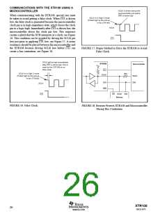
When communicating with the XTR108, special care must
be taken to avoid getting a false clock. When CS1 is driven
low, the false clock is generated because the microcontroller
clock pin is in high-impedance state, which forces the clock
pin to a logic high. Immediately after CS1 is driven low, the
microcontroller drives the clock pin low. This sequence
creates a glitch that the XTR interprets as a clock; see Figure
16. This condition can be avoided by driving the SCLK pin
low just prior to applying CS1 low; see Figure 17. A series
resistance should be placed between the microcontroller and
the XTR108 because driving SCLK low before CS1 can
create a bus contention; see Figure 18.
SCLK is in High Z mode
(Pulled high by the pull-up
in the XTR108)
SCLK
CS1
FIGURE 17. Proper Method to Drive the XTR108 to Avoid
False Clock.
SCLK will be high immediately
after CS1 is driven low. This is
seen by the XTR108 as an
false clock.
XTR108
Microcontroller
VCC
CS1
SCLK is in High Z mode
(Pulled high by the pull-up
in the XTR108)
1kΩ
SCLK
SCLK
DIO
DIO
CS2
SCLK
CS SCLK DIO
Memory
CS1
FIGURE 16. False Clock.
FIGURE 18. Resistor Protects XTR108 and Microcontroller
During Bus Contention.
XTR108
26
SBOS187C
www.ti.com

 BB [ BURR-BROWN CORPORATION ]