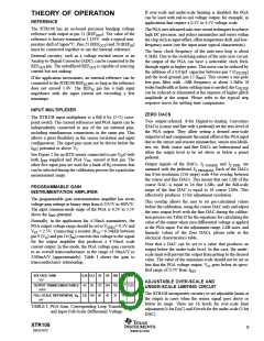
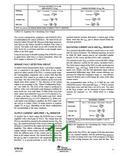
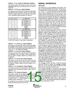
VOLTAGE REFERRED TO VO PIN
WITH RESPECT TO IRET
CURRENT REFERRED TO IOUT PIN
IZERO = IZ PROGRAM + IZ COARSE + IZ FINE
175VREF
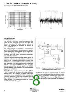
OVERALL
PROGRAM
VZERO = VZ PROGRAM + VZ COARSE + VZ FINE
3.5VREF
IZ PROGRAM
=
VZ PROGRAM
=
8RVI
8
5VREF N13
VREF N13
IZ COARSE
=
•
VZ COARSE
=
•
COARSE DAC
FINE DAC
8RVI
4
80
4
5VREF N12
VREF N12
IZ FINE
=
•
VZ FINE
=
•
8RVI
64
80
64
NOTE: N13 and N12 are assigned decimal values of registers 13 and 12, respectively.
TABLE II. Equations for Calculating Zero Output.
matched internal resistors determines a current gain of this
block. Note that the IOUT pin is always biased below the
substrate potential.
The circuit is designed for compliance with NAMUR NE43
recommendation for sensor interfaces. The limit levels are
listed in Tables VII and VIII. Because of the large step sizes,
units that use this feature should be checked if the value is
critical. The under-scale limit circuit will override the Zero
DAC level if it is set lower and there is not enough sensor
offset at the PGA input.
EXCITATION CURRENT DACS AND RSET RESISTOR
Two matched adjustable reference current sources are avail-
able for sensor excitation. The defining equations are given
in Table III. Both current sources are controlled simulta-
neously by the coarse and fine DACs with a pedestal.
It may be necessary to disable limiting if the XTR108 is used
in applications other than a 4-20mA transmitter, where the
PGA output is between 0.5V and 4.5V.
The external resistor RSET is used to convert the REF voltage
into the reference current for the sensor excitation DACs.
The total current output of the DACs is split, producing two
references: IREF1 and IREF2. Both of the current references
match very closely over the full adjustment range without
mismatched differential steps. Both current reference out-
puts must be within the compliance range, i.e.: one reference
cannot be floated since it will change the value of the other
current source.
SENSOR FAULT DETECTION CIRCUIT
To detect sensor burnout and/or short, a set of four compara-
tors is connected to the inputs of the PGA. If any of the
inputs are taken outside of the PGA’s common-mode range,
the corresponding comparator sets a sensor fault flag that
causes the PGA output to go either to the upper or lower
error limit. The state of the fault condition can be read in the
digital form from register 3. The direction of the analog
output is set according to the “Alarm Configuration Regis-
ter” (see Table X). The level of the output is produced as
follows: if the over-scale/under-scale limiting is enabled, the
error levels are: over-scale limit +2LSBs of the over-scale
DAC, about 1mA referred to IOUT or 0.125V referred to VO,
of under-scale limit –2LSBs of the under-scale DAC, about
0.4mA referred to IOUT or 0.05V referred to VO. If the over-
scale/under-scale limiting is disabled, the PGA output volt-
age will go to within 150mV of either positive or negative
supply (VS or IRET), depending on the alarm configuration
bit corresponding to the error condition.
The recommended value of RSET is 12.1kΩ for use with
100Ω RTD sensors. This generates IREF1, 2 = 492µA currents
when both coarse and fine DACs are set to zero. The value
of the RSET resistor can be increased if lower reference
currents are required, i.e.: for 1000Ω RTD or a bridge
sensor.
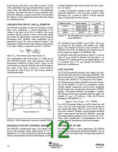
REFERENCE CURRENT
OVERALL
PROGRAM
IREF1, 2 = IREF PROGRAM + IREF COARSE + IREF FINE
5VREF
IREF PROGRAM
=
RSET
VREF N11
IREF COARSE
=
•
COARSE DAC
FINE DAC
RSET
64
OUTPUT CURRENT AMPLIFIER + RVI RESISTOR
VREF
N10
IREF FINE
=
•
RSET 1024
To produce the 4-20mA output, the XTR108 uses a current
amplifier with a fixed gain of 50A/A. The voltage from the
PGA is converted to current by the external resistor, RVI. Pin
IRET, the common potential of the circuit (substrate and local
ground), is connected to the output and inverting input of the
amplifier. This allows collecting all external and internal
supply currents, sensor return current, and leakage currents
from the different parts of the system and accounting for
them in the output current. The current from RVI flows into
the pin IIN that is connected to the noninverting input and
therefore, is at ground potential as well. The ratio of two
NOTE: N11 and N10 are the decimal values of registers 11 and 10,
respectively.
TABLE III. Equations for Calculating the Values of Each
Reference Current.
Similar to the Zero DACs, the outputs of the fine and coarse
DAC are summed together with the pedestal IREF PROGRAM
.
Each of the excitation DACs has 8-bit resolution (256 steps)
with 4-bit overlap between the coarse and the fine. This
XTR108
SBOS187C
11
www.ti.com

 BB [ BURR-BROWN CORPORATION ]