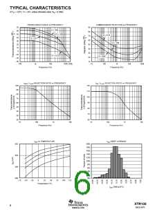
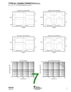
TYPICAL CHARACTERISTICS (Cont.)
At TA = +25°C, V+ = 24V, unless otherwise noted. RVI = 6.34kΩ.
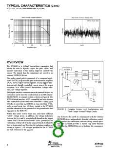
INPUT NOISE POWER DENSITY
1000
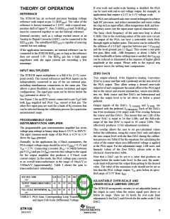
PGA PEAK-TO-PEAK NOISE (RTI)
BW: 0.1Hz to 10Hz
100
CFILT = 0.01
10
5s/div
1
10
100
1k
10k
Frequency (Hz)
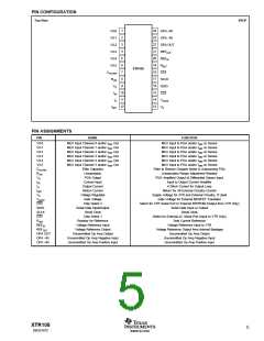
OVERVIEW
The XTR108 is a 4-20mA current-loop transmitter that
allows the user to digitally adjust the gain, offset, and
linearity correction of the analog output to calibrate the
sensor. The digital data for adjustment are stored in an
external EEPROM device.
EE PROM
SDIO
SCLK
CS1
Isolation
Couplers
Calibration
System
The analog signal path is composed of a compound multi-
plexer (MUX), programmable gain instrumentation amplifier
(PGA), and an output current amplifier. Analog support func-
tions include digitally controlled current sources for sensor
excitation, PGA offset control, linearization, voltage refer-
ence, and voltage regulator.
Calib
GND
XTR108
IO
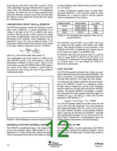
The digital interface communicates with external devices for
calibration and to store the resultant data in an SPI compat-
ible EEPROM. A complete system is shown in Figure 1. The
XTR108 serial interface is SPI compatible and only requires
four connections to the calibration controller: a serial clock
(SCLK), a serial data line (SDIO), a chip select line (CS1),
and a ground sense line. All logic signals to the XTR108
must be referenced to the potential of the ground sense line
(IRET pin on the XTR108).
RV
PS
IRET
TX
GND
RX
GND
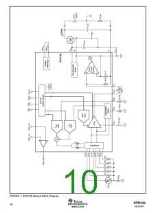
FIGURE 1. Complete System Level Configuration with
Three Unique Ground Voltage Levels.
Within this entire system there may exist three different
“GND” voltage levels. In addition, the voltage difference
between the IRET and IO potential will depend on the output
current level. It is not certain that the “GND” potential of the
calibration system will be at the same potential of either the
IRET or IO potential, and therefore the isolation couplers are
shown in Figure 1. All voltages specified for the XTR108
are with reference to the IRET pin.
The XTR108 also needs to communicate with the external
EEPROM device independently from the calibration control-
ler to retrieve the calibration constants during normal opera-
tion. The XTR108 provides a second chip select function
(CS2) for the EEPROM device to facilitate this communica-
tion.
XTR108
8
SBOS187C
www.ti.com

 BB [ BURR-BROWN CORPORATION ]