TSC2005
www.ti.com
SBAS379–DECEMBER 2006
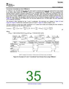
Conversion Controlled by Host (TSMode 3)
In TSMode 3, the TSC2005 detects when the touch panel is touched and causes the internal Pen-Touch signal
to be active, which lowers the PINTDAV output, if it is programmed as PENIRQ. The host recognizes the
interrupt request. Instead of starting a sequence in the TSC2005, which then reads each coordinate in turn, the
host must now control all aspects of the conversion. Generally, upon receiving the interrupt request, the host
turns on the X drivers. (NOTE: If drivers are not turned on, the device detects this condition and turns them on
before the scan starts. This situation is why the event of turn on drivers is shown as optional in Figure 34 and
Figure 35.) After waiting for the settling time, the host then addresses the TSC2005 again, this time requesting
an X coordinate conversion.
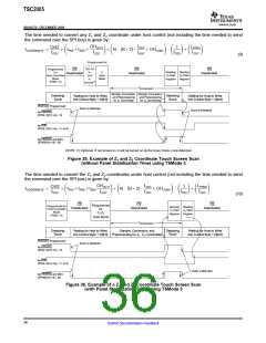
The process is then repeated for the Y and Z coordinates. The processes are outlined in Figure 34 and
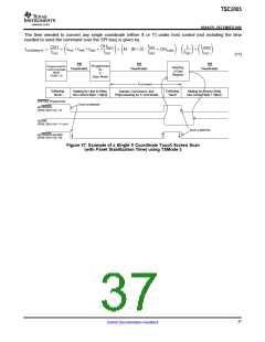
Figure 35. Figure 34 shows two consecutive scans on X and Y. Figure 35 shows a single Z scan.
The time needed to convert any single coordinate X or Y under host control (not including the time needed to
send the command over the SPI bus) is given by:
f
LPPRO
fOSC
OHDLY2
fOSC
OH1
fOSC
1
fOSC
tCOORDINATE
+
OSC )OHCONV
fADC
ǒ
) tPRE)tSNS)
Ǔ)ǒN @ B)2 @
(
)
Ǔ@ ǒ Ǔ)ǒ Ǔ
(8)
Where:
OHDLY2 = total overhead time for tPRE and tSNS = 6 internal clock cycles.
Programmed for:
Programmed for:
Turn On
Programmed
for Host-
Controlled
Mode
(PSM = 0)
CS
Deactivated X+ and
Turn On
X
CS
Deactivated
CS
Deactivated
CS
Deactivated
Y
Scan
Reading
X-Data
Register
Reading
Y-Data
Register
Y+ and
Y-
Scan
Mode
X-
Mode
(1)
(1)
Drivers
Drivers
tCOORDINATE
tCOORDINATE
Sample, Conversion,
and Preprocessing
for X Coordinate
Sample, Conversion,
and Preprocessing
for Y Coordinate
Waiting for Host to
Write Into Control
Byte 1 D[6:3]
Detecting
Touch
Waiting for Host to Write Into
Control Byte 1 D[6:3]
Detecting Waiting for Host to Write Into
Detecting
Touch
Control Byte 1 D[6:3]
Touch
Touch is Detected
PINTDAV Programmed:
Touch is Detected
Touch is Detected
As PENIRQ,
CFR2, D[15:14] = 10
As DAV,
CFR2, D[15:14] = 11 or 01
As PENIRQ and DAV,
CFR2, D[15:14] = 00
NOTE: (1) Optional. If not turned on, it will be turned on by the Scan mode, once detected.
Figure 34. Example of X and Y Coordinate Touch Screen Scan using TSMode 3
35
Submit Documentation Feedback

 BB [ BURR-BROWN CORPORATION ]