TSC2005
www.ti.com
SBAS379–DECEMBER 2006
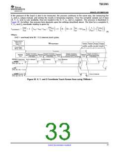
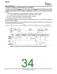
If the pressure of the touch is also to be measured, the process continues in the same way, but measuring the
Z1 and Z2 values instead, and storing the results in temporary registers. Once the complete sample set of data
(X, Y, Z1, and Z2) are available, they are loaded in the X, Y, Z1, and Z2 registers. This process is illustrated in
Figure 32. As before, this process time depends upon the settings described above. The time for a complete X,
Y, Z1, and Z2 coordinate reading is given by:
f
LPPRO
fOSC
OHDLY1
fOSC
OH2
fOSC
1
fOSC
OSC )OHCONV
@
)
)3 @ ǒ
Ǔ)4 @ N @ ǒB)2 @
(
)
Ǔ ǒ Ǔ ǒ Ǔ
ǒ
Ǔ
tCOORDINATE
+
tPVS)tPRE)tSNS
)
fADC
(6)
Where:
OH2 = overhead time #2 = 3.5 internal clock cycles.
Programmed for
Self-Control
(PSM = 1)
Reading Reading Reading Reading
Z1-Data Z2-Data
Register Register Register Register
CS Deactivated
X-Data
Y-Data
X-Y-Z1-Z2 Scan Mode
(Control Byte1
D[6:3] = 0001)
tCOORDINATE
Sample, Conversion,
and Preprocessing for
Z1 Coordinate and Z2 Coordinate
Sample, Conversion,
and Preprocessing for
Y Coordinate
Sample, Conversion,
and Preprocessing for
X Coordinate
Sample, Conversion,
and Preprocessing for
Y Coordinate
Detecting
Touch
Detecting
Touch
Detecting
Touch
Detecting
Touch
PINTDAV Programmed:
Touch is Detected
Touch is Detected
Touch is Detected
As PENIRQ,
CFR2, D[15:14] = 10
As DAV,
CFR2, D[15:14] = 11 or 01
Touch is Detected
As PENIRQ and DAV,
CFR2, D[15:14] = 00
Figure 32. X, Y, and Z Coordinate Touch Screen Scan using TSMode 1
33
Submit Documentation Feedback

 BB [ BURR-BROWN CORPORATION ]