ꢀ ꢁꢂ ꢃ ꢄ ꢅ ꢆ
www.ti.com
SLES100 − DECEMBER 2003
Register Map
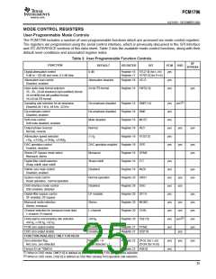
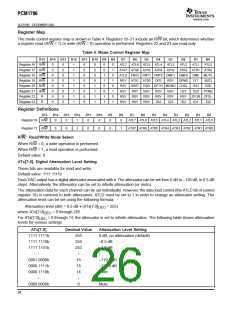
The mode control register map is shown in Table 4. Registers 16–21 include an R/W bit, which determines whether
a register read (R/W = 1) or write (R/W = 0) operation is performed. Registers 22 and 23 are read-only.
Table 4. Mode Control Register Map
B15
Register 16 R/W
Register 17 R/W
Register 18 R/W
Register 19 R/W
Register 20 R/W
Register 21 R/W
B14
0
B13
0
B12
1
B11
0
B10 B9 B8
B7
B6
B5
B4
B3
B2
B1
B0
0
0
0
0
1
1
1
1
0
0
1
1
0
0
1
1
0
1
0
1
0
1
0
1
ATL7 ATL6 ATL5 ATL4
ATL3
ATL2
ATL1
ATL0
0
0
1
0
ATR7 ATR6 ATR5 ATR4 ATR3
ATLD FMT2 FMT1 FMT0 DMF1 DMF0 DME MUTE
ATR2 ATR1 ATR0
0
0
1
0
0
0
1
0
REV ATS1 ATS0 OPE
RSV
DFMS
FLT
OS1
DZ0
INZD
OS0
0
0
1
0
RSV SRST DSD DFTH MONO CHSL
0
0
1
0
RSV
RSV
RSV
RSV
RSV
RSV
RSV
RSV
RSV
RSV
RSV
ID4
RSV
RSV
ID3
DZ1
RSV
ID2
PCMZ
Register 22
Register 23
R
R
0
0
1
0
ZFGR ZFGL
0
0
1
0
ID1
ID0
Register Definitions
B15
B14
B13
B12
B11
B10
B9
B8
B7
B6
B5
B4
B3
B2
B1
B0
Register 16 R/W
0
0
1
0
0
0
0
ATL7 ATL6 ATL5 ATL4 ATL3 ATL2 ATL1 ATL0
Register 17 R/W
0
0
1
0
0
0
1
ATR7 ATR6 ATR5 ATR4 ATR3 ATR2 ATR1 ATR0
R/W: Read/Write Mode Select
When R/W = 0, a write operation is performed.
When R/W = 1, a read operation is performed.
Default value: 0
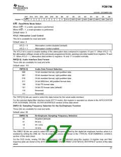
ATx[7:0]: Digital Attenuation Level Setting
These bits are available for read and write.
Default value: 1111 1111b
Each DAC output has a digital attenuator associated with it. The attenuator can be set from 0 dB to –120 dB, in 0.5-dB
steps. Alternatively, the attenuator can be set to infinite attenuation (or mute).
The attenuation data for each channel can be set individually. However, the data load control (the ATLD bit of control
register 18) is common to both attenuators. ATLD must be set to 1 in order to change an attenuator setting. The
attenuation level can be set using the following formula:
Attenuation level (dB) = 0.5 dB • (ATx[7:0]
– 255)
DEC
where ATx[7:0]
= 0 through 255
DEC
For ATx[7:0]
levels for various settings:
= 0 through 14, the attenuator is set to infinite attenuation. The following table shows attenuation
DEC
ATx[7:0]
1111 1111b
1111 1110b
1111 1101b
L
Decimal Value
Attenuation Level Setting
255
254
253
L
0 dB, no attenuation (default)
–0.5 dB
–1.0 dB
L
0001 0000b
0000 1111b
0000 1110b
L
16
15
14
L
–119.5 dB
–120.0 dB
Mute
L
0000 0000b
0
Mute
26

 BB [ BURR-BROWN CORPORATION ]