ꢀ ꢁꢂ ꢃ ꢄꢅ ꢆ
www.ti.com
SLES100 − DECEMBER 2003
MODE CONTROL REGISTERS
User-Programmable Mode Controls
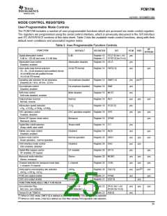
The PCM1796 includes a number of user-programmable functions which are accessed via mode control registers.
The registers are programmed using the serial control interface, which is previously discussed in the SPI Interface
2
and I C INTERFACE sections of this data sheet. Table 3 lists the available mode-control functions, along with their
default reset conditions and associated register index.
Table 3. User-Programmable Function Controls
DF
BYPASS
FUNCTION
Digital attenuation control
DEFAULT
REGISTER
BIT
PCM
DSD
0 dB
Attenuation disabled
Register 16 ATL[7:0] (for L-ch)
Register 17 ATR[7:0] (for R-ch)
yes
0 dB to –120 dB and mute, 0.5 dB step
Attenuation load control
Disabled, enabled
Register 18 ATLD
yes
yes
2
Input audio data format selection
24-bit I S format
Register 18 FMT[2:0]
yes
16-, 20-, 24-bit standard (right-justified) format
24-bit MSB-first left-justified format
2
16-/24-bit I S format
(1)
yes
Sampling rate selection for de-emphasis
Disabled,44.1 kHz, 48 kHz, 32 kHz
De-emphasis disabled
De-emphasis disabled
Mute disabled
Register 18 DMF[1:0]
Register 18 DME
Register 18 MUTE
Register 19 REV
yes
yes
yes
yes
yes
yes
De-emphasis control
Disabled, enabled
Soft mute control
Soft mute disabled, enabled
Output phase reversal
Normal, reverse
Normal
yes
yes
Attenuation speed selection
×1 f
Register 19 ATS[1:0]
S
×1f , ×(1/2)f , ×(1/4)f , ×(1/8)f
S
S
S
S
DAC operation control
Enabled, disabled
DAC operation enabled Register 19 OPE
yes
yes
yes
Stereo DF bypass mode select
Monaural, stereo
Monaural
Register 19 DFMS
Register 19 FLT
Digital filter rolloff selection
Sharp rolloff, slow rolloff
Sharp rolloff
Disabled
yes
yes
yes
yes
yes
yes
yes
yes
yes
Infinite zero mute control
Disabled, enabled
Register 19 INZD
Register 20 SRST
Register 20 DSD
Register 20 DFTH
Register 20 MONO
Register 20 CHSL
Register 20 OS[1:0]
yes
yes
System reset control
Reset operation , normal operation
Normal operation
Disabled
yes
yes
DSD interface mode control
DSD enabled, disabled
Digital-filter bypass control
DF enabled, DF bypass
DF enabled
Stereo
yes
yes
yes
yes
yes
Monaural mode selection
Stereo, monaural
yes
yes
Channel selection for monaural mode data
L-channel, R-channel
L-channel
(2)
yes
Delta-sigma oversampling rate selection
×64 f
S
×64 f , ×128 f , ×32 f
S
S
S
PCM zero output enable
Enabled
Disabled
Register 21 PCMZ
Register 21 DZ[1:0]
DSD zero output enable
yes
yes
FUNCTION AVAILABLE ONLY FOR READ
Zero detection flag
Not zero, zero detected
Not zero = 0
Zero detected = 1
Register 22 ZFGL (for L-ch)
ZFGR (for R-ch)
yes
yes
yes
Device ID (at TDMCA)
−
Register 23 ID[4:0]
(1)
(2)
When in DSD mode, DMF[1:0] is defined as DSD filter (analog FIR) performance selection.
When in DSD mode, OS[1:0] is defined as DSD filter (analog FIR) operation rate selection.
25

 BB [ BURR-BROWN CORPORATION ]