ꢀ
ꢁ
ꢂ
ꢃ
ꢄ
ꢅ
ꢆ
www.ti.com
SLES100 − DECEMBER 2003
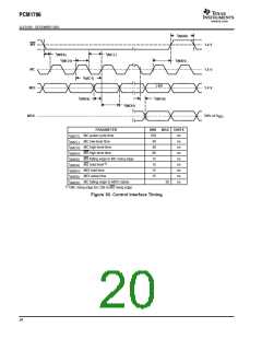
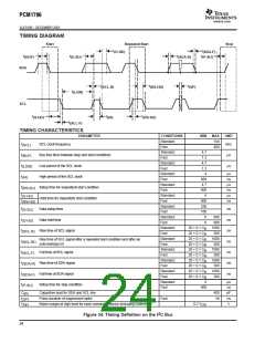
TIMING DIAGRAM
Start
Repeated Start
(D-HD)
Stop
t
t
(SDA-F)
t
t
t
t
(P-SU)
(BUF)
(D-SU)
(SDA-R)
SDA
t
t
t
(SP)
(SCL-R)
(RS-HD)
t
(LOW)
SCL
t
t
t
(RS-SU)
(S-HD)
(HI)
t
(SCL-F)
TIMING CHARACTERISTICS
PARAMETER
CONDITIONS
Standard
Fast
MIN MAX
100
400
4.7
UNIT
f
t
t
t
t
SCL clock frequency
kHz
(SCL)
(BUF)
(LOW)
(HI)
Standard
Fast
Bus free time between stop and start conditions
Low period of the SCL clock
High period of the SCL clock
Setup time for (repeated) start condition
Hold time for (repeated) start condition
Data setup time
µs
µs
1.3
Standard
Fast
4.7
1.3
Standard
Fast
4
µs
ns
µs
ns
µs
ns
600
4.7
Standard
Fast
(RS-SU)
600
4
t
t
Standard
Fast
(S-HD)
600
250
100
(RS-HD)
Standard
Fast
t
t
t
t
t
t
t
t
ns
ns
ns
ns
ns
ns
ns
(D-SU)
Standard
Fast
0
0
900
900
Data hold time
(D-HD)
Standard
Fast
20 + 0.1 C
20 + 0.1 C
20 + 0.1 C
20 + 0.1 C
20 + 0.1 C
20 + 0.1 C
20 + 0.1 C
20 + 0.1 C
20 + 0.1 C
20 + 0.1 C
1000
300
B
B
B
B
B
B
B
B
B
Rise time of SCL signal
(SCL-R)
(SCL-R1)
(SCL-F)
(SDA-R)
(SDA-F)
(P-SU)
Standard
Fast
1000
300
Rise time of SCL signal after a repeated start condition and after an
acknowledge bit
Standard
Fast
1000
300
Fall time of SCL signal
Rise time of SDA signal
Fall time of SDA signal
Setup time for stop condition
Standard
Fast
1000
300
Standard
Fast
1000
300
B
4
Standard
Fast
µs
ns
pF
ns
V
600
C
Capacitive load for SDA and SCL line
Pulse duration of suppressed spike
400
50
(B)
t
Fast
(SP)
V
NH
Noise margin at high level for each connected device (including hysteresis)
0.2 V
DD
2
Figure 34. Timing Definition on the I C Bus
24

 BB [ BURR-BROWN CORPORATION ]