ꢀ
ꢁ
ꢂ
ꢃ
ꢄ
ꢅ
ꢆ
www.ti.com
SLES100 − DECEMBER 2003
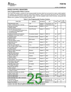
2
I C INTERFACE
2
The PCM1796 supports the I C serial bus and the data transmission protocol for standard and fast mode as a slave
2
device. This protocol is explained in I C specification 2.0.
2
In I C mode, the control terminals are changed as follows.
TERMINAL NAME
TDMCA NAME
ADR0
PROPERTY
Input
DESCRIPTION
2
I C address 0
MS
MDI
MC
2
I C address 1
ADR1
Input
2
I C clock
SCL
Input
2
I C data
MDO
SDA
Input/output
Slave Address
MSB
1
LSB
R/W
0
0
1
1
ADR1
ADR0
The PCM1796 has 7 bits for its own slave address. The first five bits (MSBs) of the slave address are factory preset
to 10011. The next two bits of the address byte are the device select bits which can be user-defined by the ADR1
and ADR0 terminals. A maximum of four PCM1796s can be connected on the same bus at one time. Each PCM1796
responds when it receives its own slave address.
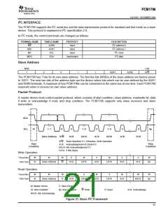
Packet Protocol
A master device must control packet protocol, which consists of start condition, slave address, read/write bit, data
if write or acknowledge if read, and stop condition. The PCM1796 supports only slave receivers and slave
transmitters.
SDA
SCL
St
1−7
8
9
1−8
9
1−8
9
9
Sp
Slave Address R/W
ACK
DATA
ACK
DATA
ACK
ACK
R/W: Read Operation if 1; Otherwise, Write Operation
ACK: Acknowledgement of a Byte if 0
NACK: Not Acknowledgement if 1
DATA: 8 Bits (Byte)
Start
Condition
Stop
Condition
Write Operation
Transmitter
Data Type
M
M
M
S
M
S
M
S
S
M
St
Slave Address
W
ACK
DATA
ACK
DATA
ACK
ACK
Sp
Read Operation
Transmitter
Data Type
M
M
M
S
S
M
S
M
M
M
St
Slave Address
R
ACK
DATA
ACK
DATA
ACK
NACK
Sp
M: Master Device
S: Slave Device
St: Start Condition
Sp: Stop Condition
W: Write
R: Read
ACK: Acknowledge
NACK: Not Acknowledge
2
Figure 31. Basic I C Framework
21

 BB [ BURR-BROWN CORPORATION ]