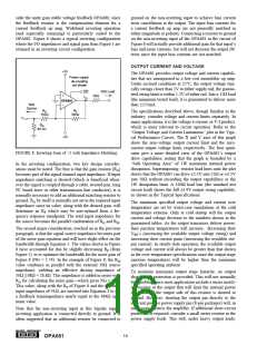
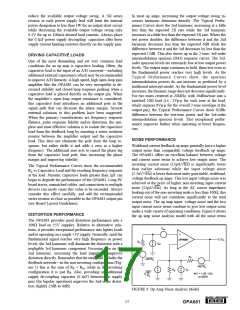
internal dissipation will occur if the load requires current to
be forced into the output for positive output voltages or
sourced from the output for negative output voltages. This
puts a high current through a large internal voltage drop in
the output transistors. The Output Voltage and Current
Limitations plot shown in the Typical Performance Curves
include a boundary for 1W maximum internal power dissi-
pation under these conditions.
will reduce the bandwidth, while decreasing it will give a
more peaked frequency response. The 402Ω feedback resis-
tor used in the typical performance specifications at a gain
of +2 on ±5V supplies is a good starting point for design.
Note that a 453Ω feedback resistor, rather than a direct short,
is recommended for the unity gain follower application. A
current feedback op amp requires a feedback resistor even in
the unity gain follower configuration to control stability.
d) Connections to other wideband devices on the board
may be made with short direct traces or through on-board
transmission lines. For short connections, consider the trace
and the input to the next device as a lumped capacitive load.
Relatively wide traces (50mils to 100mils) should be used,
preferably with ground and power planes opened up around
them. Estimate the total capacitive load and set RS from the
plot of recommended RS versus Capacitive Load. Low
parasitic capacitive loads (< 5pF) may not need an RS since
the OPA681 is nominally compensated to operate with a 2pF
parasitic load. If a long trace is required, and the 6dB signal
loss intrinsic to a doubly-terminated transmission line is
acceptable, implement a matched impedance transmission
line using microstrip or stripline techniques (consult an ECL
design handbook for microstrip and stripline layout tech-
niques). A 50Ω environment is normally not necessary on
board, and in fact, a higher impedance environment will
improve distortion as shown in the Distortion vs Load plots.
With a characteristic board trace impedance defined based
on board material and trace dimensions, a matching series
resistor into the trace from the output of the OPA681 is used
as well as a terminating shunt resistor at the input of the
destination device. Remember also that the terminating
impedance will be the parallel combination of the shunt
resistor and the input impedance of the destination device:
this total effective impedance should be set to match the
trace impedance. The high output voltage and current capa-
bility of the OPA681 allows multiple destination devices to
be handled as separate transmission lines, each with their
own series and shunt terminations. If the 6dB attenuation of
a doubly-terminated transmission line is unacceptable, a
long trace can be series-terminated at the source end only.
Treat the trace as a capacitive load in this case and set the
series resistor value as shown in the plot of RS vs Capacitive
Load. This will not preserve signal integrity as well as a
doubly-terminated line. If the input impedance of the desti-
nation device is low, there will be some signal attenuation
due to the voltage divider formed by the series output into
the terminating impedance.
BOARD LAYOUT GUIDELINES
Achieving optimum performance with a high frequency
amplifier like the OPA681 requires careful attention to
board layout parasitics and external component types. Rec-
ommendations that will optimize performance include:
a) Minimize parasitic capacitance to any AC ground for
all of the signal I/O pins. Parasitic capacitance on the output
and inverting input pins can cause instability: on the non-
inverting input, it can react with the source impedance to
cause unintentional bandlimiting. To reduce unwanted ca-
pacitance, a window around the signal I/O pins should be
opened in all of the ground and power planes around those
pins. Otherwise, ground and power planes should be unbro-
ken elsewhere on the board.
b) Minimize the distance (< 0.25") from the power supply
pins to high frequency 0.1µF decoupling capacitors. At the
device pins, the ground and power plane layout should not
be in close proximity to the signal I/O pins. Avoid narrow
power and ground traces to minimize inductance between
the pins and the decoupling capacitors. The power supply
connections (on pins 4 and 7) should always be decoupled
with these capacitors. An optional supply decoupling ca-
pacitor across the two power supplies (for bipolar operation)
will improve 2nd harmonic distortion performance. Larger
(2.2µF to 6.8µF) decoupling capacitors, effective at lower
frequency, should also be used on the main supply pins.
These may be placed somewhat farther from the device and
may be shared among several devices in the same area of the
PC board.
c) Careful selection and placement of external compo-
nents will preserve the high frequency performance of
the OPA681. Resistors should be a very low reactance type.
Surface-mount resistors work best and allow a tighter over-
all layout. Metal-film and carbon composition, axially-leaded
resistors can also provide good high frequency performance.
Again, keep their leads and PC board trace length as short as
possible. Never use wirewound type resistors in a high
frequency application. Since the output pin and inverting
input pin are the most sensitive to parasitic capacitance,
always position the feedback and series output resistor, if
any, as close as possible to the output pin. Other network
components, such as non-inverting input termination resis-
tors, should also be placed close to the package. Where
double-side component mounting is allowed, place the feed-
back resistor directly under the package on the other side of
the board between the output and inverting input pins. The
frequency response is primarily determined by the feedback
resistor value as described previously. Increasing its value
e) Socketing a high speed part like the OPA681 is not
recommended. The additional lead length and pin-to-pin
capacitance introduced by the socket can create an ex-
tremely troublesome parasitic network which can make it
almost impossible to achieve a smooth, stable frequency
response. Best results are obtained by soldering the OPA681
onto the board. If socketing for the DIP package is desired,
high frequency flush-mount pins (e.g., McKenzie Technol-
ogy #710C) can give good results.
®
20
OPA681

 BB [ BURR-BROWN CORPORATION ]