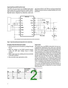
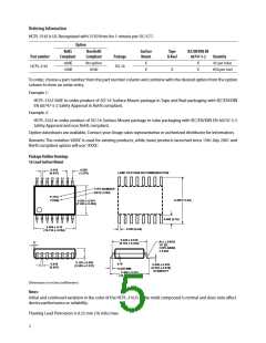
Typical Fault Protected IGBT Gate Drive Circuit
The HCPL-316J is an easy-to-use, intelligent gate driver
age lockout (UVLO),“soft”IGBT turn-off and isolated fault
feedback provide maximum design flexibility and circuit
protection.
which makes IGBT V fault protection compact, afford-
CE
able, and easy-to-implement. Features such as user con-
figurable inputs, integrated V detection, under volt-
CE
HCPL-316J
1
2
3
4
5
6
7
8
V
V
V
V
16
15
DESAT 14
IN+
IN-
E
C
BLANK
*
V
LED2+
D
DESAT
100 Ω
CC1
+
–
+
–
µC
V
F
GND1
V
13
12
11
10
9
CC2
R
F
+
–
+
–
+
–
RESET
FAULT
V
C
R
G
*
V
V
CE
CE
V
OUT
V
V
+
–
*
LED1+
EE
V
V
EE
LED1-
R
PULL-DOWN
* THESE COMPONENTS ARE ONLY REQUIRED WHEN NEGATIVE GATE DRIVE IS IMPLEMENTED.
Figure 1. Typical desaturation protected gate drive circuit, noninverting.
Description of Operation during Fault Condition
Output Control
1. DESATterminalmonitorstheIGBTV voltagethrough
The outputs (V
and FAULT) of the HCPL-316J are con-
CE
OUT
D
.
trolled by the combination of V , UVLO and a detected
DESAT
IN
IGBT Desat condition. As indicated in the below table, the
HCPL-316J can be configured as inverting or non-invert-
2. When the voltage on the DESAT terminal exceeds
7volts, the IGBT gate voltage (V
lowered.
) is slowly
OUT
ing using the V or V inputs respectively. When an in-
IN+
IN-
verting configuration is desired, V must be held high
IN+
3. FAULT output goes low, notifying the microcontroller
of the fault condition.
and V toggled. When a non-inverting configuration is
IN-
desired, V must be held low and V
toggled. Once
IN-
IN+
4. Microcontroller takes appropriate action.
UVLO is not active (V
- V > V
), V
UVLO
is allowed to
OUT
CC2
E
go high, and the DESAT (pin 14) detection feature of the
HCPL-316J will be the primary source of IGBT protection.
UVLO is needed to ensure DESAT is functional. Once V
U-
<
> 11.6 V, DESAT will remain functional until V
VLO+
UVLO-
12.4 V. Thus, the DESAT detection and UVLO features of
the HCPL-316J work in conjunction to ensure constant
IGBT protection.
Desat Condition
Detected on
Pin 14
X
Pin 6
UVLO
(FAULT)
Output
X
V
X
X
Low
X
V
X
X
X
High
Low
(V - V )
V
OUT
IN+
IN-
CC2
E
Active
Low
Low
Low
Low
High
X
X
X
Yes
X
X
Low
X
X
High
Not Active
No
High
2

 AVAGO [ AVAGO TECHNOLOGIES LIMITED ]