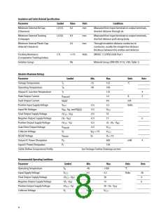
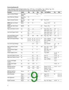
Electrical Specifications (DC)
Unless otherwise noted, all typical values at T = 25°C, V
= 5 V, and V
- V = 30 V, V - V = 0 V;
EE E EE
A
CC1
CC2
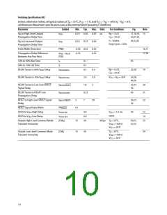
all Minimum/Maximum specifications are at Recommended Operating Conditions.
Parameter
Symbol
Min.
Typ.
Max.
Units Test Conditions
Fig.
Note
Logic Low Input Voltages
VIN+L, VIN-L
,
0.8
V
VRESETL
Logic High Input Voltages
Logic Low Input Currents
VIN+H, VIN-H
VRESETH
,
2.0
IIN+L, IIN-L
,
-0.5
5.0
-0.4
mA
VIN = 0.4 V
IRESETL
FAULT Logic Low Output
Current
IFAULTL
IFAULTH
IOH
12
VFAULT = 0.4 V
VFAULT = VCC1
30
31
FAULT Logic High Output
Current
-40
µA
A
High Level Output Current
-0.5
-2.0
0.5
2.0
90
-1.5
2.3
VOUT = VCC2 - 4 V
VOUT = VCC2 - 15 V
VOUT = VEE + 2.5 V
VOUT = VEE + 15 V
VOUT - VEE = 14 V
3, 8,
32
7
5
7
5
8
Low Level Output Current
IOL
4, 9,
33
Low Level Output Current
During Fault Condition
IOLF
VOH
160
230
mA
V
5, 34
High Level Output Voltage
VC - 3.5 VC - 2.5 VC - 1.5
IOUT = -100 mA
IOUT = -650 µA
IOUT = 0
6, 8,
35
9, 10, 11
VC -2.9
VC - 2.0 VC - 1.2
VC
Low Level Output Voltage
VOL
0.17
0.5
22
11
5
IOUT = 100 mA
7, 9,
36
26
High Level Input Supply
Current
ICC1H
ICCIL
ICC2
17
mA
VIN+ = VCC1 = 5.5 V,
VIN- = 0 V
10, 37
38
Low Level Input Supply
Current
6
VIN+ = VIN- = 0 V,
VCC1 = 5.5 V
Output Supply Current
2.5
VOUT open
11, 12, 11
39, 40
Low Level Collector Current
High Level Collector Current
ICL
0.3
0.3
1.8
-0.4
1.0
1.3
3.0
0
IOUT = 0
15, 59 27
15, 58 27
15, 57
ICH
IOUT = 0
IOUT = -650 µA
VE Low Level Supply
Current
IEL
-0.7
-0.5
14, 61
VE High Level Supply
Current
IEH
-0.14
0
14, 40 25
Blanking Capacitor
Charging Current
ICHG
-0.13
-0.18
-0.25
-0.25
-0.33
-0.33
VDESAT = 0 - 6 V
13, 41 11, 12
VDESAT = 0 - 6 V,
TA = 25°C - 100°C
Blanking Capacitor
Discharge Current
IDSCHG
10
50
VDESAT = 7 V
42
UVLO Threshold
VUVLO+
VUVLO-
(VUVLO+
VUVLO-
VDESAT
11.6
12.3
11.1
1.2
13.5
12.4
V
VOUT > 5 V
VOUT < 5 V
43
9, 11, 13
9, 11, 14
UVLO Hysteresis
DESAT Threshold
-
0.4
6.5
)
7.0
7.5
VCC2 - VE > VUVLO
-
16, 44 11
9

 AVAGO [ AVAGO TECHNOLOGIES LIMITED ]