Toꢀminimizeꢀdeadꢀtimeꢀinꢀaꢀgivenꢀdesign,ꢀtheꢀturnꢀonꢀofꢀ deadꢀtimeꢀwillꢀbe.ꢀTheꢀmaximumꢀdeadꢀtimeꢀisꢀequivalentꢀ
LED2ꢀshouldꢀbeꢀdelayedꢀ(relativeꢀtoꢀtheꢀturnꢀoffꢀofꢀLED1)ꢀ toꢀtheꢀdifferenceꢀbetweenꢀtheꢀmaximumꢀandꢀminimumꢀ
soꢀthatꢀunderꢀworst-caseꢀcon-ditions,ꢀtransistorꢀQ1ꢀhasꢀ propagationꢀdelayꢀdifferenceꢀspecificationsꢀasꢀshownꢀinꢀ
justꢀturnedꢀoffꢀwhenꢀtransistorꢀQ2ꢀturnsꢀon,ꢀasꢀshownꢀinꢀ Figureꢀ36.ꢀTheꢀmaximumꢀdeadꢀtimeꢀforꢀtheꢀHCPL-3120ꢀisꢀ
Figureꢀ35.ꢀTheꢀamountꢀofꢀdelayꢀnecessaryꢀtoꢀachieveꢀthisꢀ 700ꢀnsꢀ(=ꢀ350ꢀnsꢀ-ꢀ(-350ꢀns))ꢀoverꢀanꢀoperatingꢀtempera-
conditionsꢀisꢀequalꢀtoꢀtheꢀmaximumꢀvalueꢀofꢀtheꢀpropa- tureꢀrangeꢀofꢀ-40°Cꢀtoꢀ100°C.
gationꢀdelayꢀdifferenceꢀspecification,ꢀPDD
specifiedꢀtoꢀbeꢀ350ꢀnsꢀoverꢀtheꢀoperatingꢀtemperatureꢀ
rangeꢀofꢀ-40°Cꢀtoꢀ100°C.
,ꢀwhichꢀisꢀ
MAX
NoteꢀthatꢀtheꢀpropagationꢀdelaysꢀusedꢀtoꢀcalculateꢀPDDꢀ
andꢀdeadꢀtimeꢀareꢀtakenꢀatꢀequalꢀtemperaturesꢀandꢀtestꢀ
conditionsꢀsinceꢀtheꢀoptocouplersꢀunderꢀconsiderationꢀ
DelayingꢀtheꢀLEDꢀsignalꢀbyꢀtheꢀmaximumꢀpropagationꢀ areꢀtypicallyꢀmountedꢀinꢀcloseꢀproximityꢀtoꢀeachꢀotherꢀ
delayꢀdifferenceꢀensuresꢀthatꢀtheꢀminimumꢀdeadꢀtimeꢀisꢀ andꢀareꢀswitchingꢀidenticalꢀIGBTs.
zero,ꢀbutꢀitꢀdoesꢀnotꢀtellꢀaꢀdesignerꢀwhatꢀtheꢀmaximumꢀ
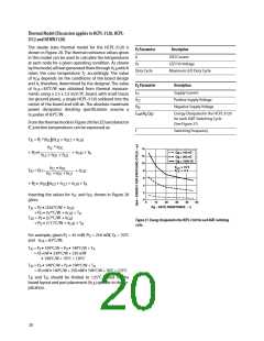
HCNWꢀ130
(mWꢁ
HCPL-ꢀ130 OPTION 060éHCPL-Jꢀ13
1000
800
700
600
500
400
ꢀ00
P
I
(mWꢁ
P
I
S
S
900
800
700
600
500
400
ꢀ00
300
(mAꢁ
(mAꢁ FOR HCPL-ꢀ130
S
S
OPTION 060
I
(mAꢁ FOR HCPL-Jꢀ13
S
300
100
0
100
0
0
35 50 75 100 135 150 175 300
– CASE TEMPERATURE – °C
0
35
50 75 100 135 150 175
T
T
– CASE TEMPERATURE – °C
S
S
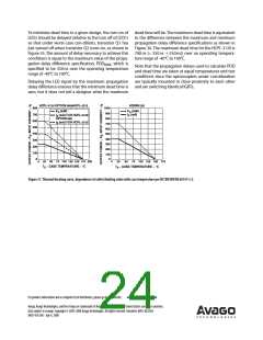
Figure 37. Thermal derating curve, dependence of safety limiting value with case temperature per IEC/EN/DIN EN 60747-5-2.
For product information and a complete list of distributors, please go to our website: www.avagotech.com
Avago, Avago Technologies, and the A logo are trademarks of Avago Technologies in the United States and other countries.
Data subject to change. Copyright © 2005-2008 Avago Technologies. All rights reserved. Obsoletes AV01-0622EN
AV02-0161EN - July 4, 2008

 AVAGO [ AVAGO TECHNOLOGIES LIMITED ]