(V ꢀ≤
F
V
)ꢀ duringꢀ commonꢀ modeꢀ transients.ꢀ Forꢀ
F(OFF)
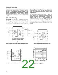
CMR with the LED On (CMR ).
H
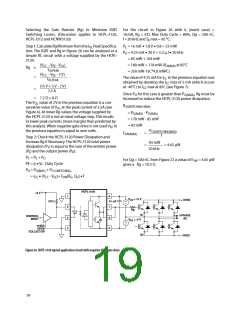
AꢀhighꢀCMRꢀLEDꢀdriveꢀcircuitꢀmustꢀkeepꢀtheꢀLEDꢀonꢀduringꢀ
commonꢀmodeꢀtransients.ꢀThisꢀisꢀachievedꢀbyꢀoverdriv-
ingꢀtheꢀLEDꢀcurrentꢀbeyondꢀtheꢀinputꢀthresholdꢀsoꢀthatꢀ
itꢀisꢀnotꢀpulledꢀbelowꢀtheꢀthresholdꢀduringꢀaꢀtransient.ꢀ
Aꢀ minimumꢀ LEDꢀ currentꢀ ofꢀ 10ꢀ mAꢀ providesꢀ adequateꢀ
R
ꢀandꢀV ꢀofꢀtheꢀlogicꢀgate.ꢀAsꢀlongꢀasꢀtheꢀlowꢀstateꢀ
SAT
SAT
voltageꢀ developedꢀ acrossꢀ theꢀ logicꢀ gateꢀ isꢀ lessꢀ thanꢀ
,ꢀtheꢀLEDꢀwillꢀremainꢀoffꢀandꢀnoꢀcommonꢀmodeꢀ
V
F(OFF)
failureꢀwillꢀoccur.
Theꢀ openꢀ collectorꢀ driveꢀ circuit,ꢀ shownꢀ inꢀ Figureꢀ 32,ꢀ
cannotꢀkeepꢀtheꢀLEDꢀoffꢀduringꢀaꢀ+dVcm/dtꢀtransient,ꢀ
sinceꢀ allꢀ theꢀ currentꢀ flowingꢀ throughꢀ C
marginꢀoverꢀtheꢀmaximumꢀI ꢀofꢀ5ꢀmAꢀtoꢀachieveꢀ25ꢀkV/
FLH
µsꢀCMR.
ꢀ mustꢀ beꢀ
LEDN
suppliedꢀ byꢀ theꢀ LED,ꢀ andꢀ itꢀ isꢀ notꢀ recommendedꢀ forꢀ
CMR with the LED Off (CMR ).
L
applica-tionsꢀ requiringꢀ ultraꢀ highꢀ CMR ꢀ performance.ꢀ
L
Aꢀ highꢀ CMRꢀ LEDꢀ driveꢀ circuitꢀ mustꢀ keepꢀ theꢀ LEDꢀ o ꢀ
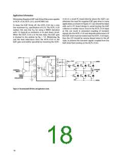
Figureꢀ33ꢀisꢀanꢀalternativeꢀdriveꢀcircuitꢀwhich,ꢀlikeꢀtheꢀrec-
ommendedꢀapplica-tionꢀcircuitꢀ(Figureꢀ25),ꢀdoesꢀachieveꢀ
ultraꢀhighꢀCMRꢀperformanceꢀbyꢀshuntingꢀtheꢀLEDꢀinꢀtheꢀ
offꢀstate.
example,ꢀduringꢀaꢀ-dV /dtꢀtransientꢀinꢀFigureꢀ31,ꢀtheꢀ
cm
currentꢀ flowingꢀ throughꢀ C
ꢀ alsoꢀ flowsꢀ throughꢀ theꢀ
LEDP
+5 V
1
8
0.1
µF
+
–
C
LEDP
V
= 18 V
CC
3
7
6
5
+
1
3
ꢀ
4
8
7
6
5
I
LEDP
V
SAT
+5 V
Q1
–
C
LEDP
ꢀ
4
• • •
• • •
C
LEDN
Rg
SHIELD
C
I
LEDN
LEDN
* THE ARROWS INDICATE THE DIRECTION
OF CURRENT FLOW DURING –dV /dt.
SHIELD
CM
+
–
V
CM
Figure 31. Equivalent circuit for figure 25 during common mode transient.
Figure 32. Not recommended open collector drive circuit.
14
13
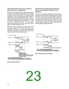
(13.ꢀ, 10.8ꢁ
1
3
ꢀ
4
8
7
6
5
10
(10.7, 9.3ꢁ
+5 V
C
C
8
6
4
3
LEDP
LEDN
(10.7, 0.1ꢁ
(13.ꢀ, 0.1ꢁ
0
SHIELD
0
5
10
15
30
(V
- V
EE
ꢁ – SUPPLY VOLTAGE – V
CC
Figure 33. Recommended LED drive circuit for ultra-high CMR.
Figure 34. Under voltage lock out.
22

 AVAGO [ AVAGO TECHNOLOGIES LIMITED ]