lowꢀmaximumꢀV ꢀspecificationꢀofꢀ0.5V.ꢀTheꢀHCPL-3120ꢀ
Applications Information
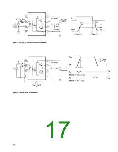
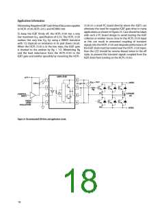
3120ꢀonꢀaꢀsmallꢀPCꢀboardꢀdirectlyꢀaboveꢀtheꢀIGBT)ꢀcanꢀ
eliminateꢀtheꢀneedꢀforꢀnegativeꢀIGBTꢀgateꢀdriveꢀinꢀmanyꢀ
applicationsꢀasꢀshownꢀinꢀFigureꢀ25.ꢀCareꢀshouldꢀbeꢀtakenꢀ
withꢀsuchꢀaꢀPCꢀboardꢀdesignꢀtoꢀavoidꢀroutingꢀtheꢀIGBTꢀ
collectorꢀorꢀemitterꢀtracesꢀcloseꢀtoꢀtheꢀHCPL-3120ꢀinputꢀ
asꢀ thisꢀ canꢀ resultꢀ inꢀ unwantedꢀ couplingꢀ ofꢀ transientꢀ
signalsꢀintoꢀtheꢀHCPL-3120ꢀandꢀdegradeꢀperformance.ꢀ(Ifꢀ
theꢀIGBTꢀdrainꢀmustꢀbeꢀroutedꢀnearꢀtheꢀHCPL-3120ꢀinput,ꢀ
thenꢀtheꢀLEDꢀshouldꢀbeꢀreverse-biasedꢀwhenꢀinꢀtheꢀo ꢀ
state,ꢀtoꢀpreventꢀtheꢀtransientꢀsignalsꢀcoupledꢀfromꢀtheꢀ
IGBTꢀdrainꢀfromꢀturningꢀonꢀtheꢀHCPL-3120.)ꢀ
EliminatingꢀNegativeꢀIGBTꢀGateꢀDriveꢀ(Discussionꢀappliesꢀ
toꢀHCPL-3120,ꢀHCPL-J312,ꢀandꢀHCNW3120)
Toꢀ keepꢀ theꢀ IGBTꢀ firmlyꢀ off,ꢀ theꢀ HCPL-3120ꢀ hasꢀ aꢀ veryꢀ
OL
realizesꢀ thisꢀ veryꢀ lowꢀV ꢀ byꢀ usingꢀ aꢀ DMOSꢀ transistorꢀ
OL
withꢀ1ꢀΩꢀ(typical)ꢀonꢀresistanceꢀinꢀitsꢀpullꢀdownꢀcircuit.ꢀ
WhenꢀtheꢀHCPL-3120ꢀisꢀinꢀtheꢀlowꢀstate,ꢀtheꢀIGBTꢀgateꢀ
isꢀ shortedꢀ toꢀ theꢀ emitterꢀ byꢀ Rgꢀ +ꢀ 1ꢀΩ.ꢀ Minimizingꢀ Rgꢀ
andꢀ theꢀ leadꢀ inductanceꢀ fromꢀ theꢀ HCPL-3120ꢀ toꢀ theꢀ
IGBTꢀgateꢀandꢀemitterꢀ(possiblyꢀbyꢀmountingꢀtheꢀHCPL-
HCPL-ꢀ130
+5 V
1
3
ꢀ
4
8
V
= 18 V
CC
+ HVDC
370 Ω
0.1 µF
+
–
7
6
5
Rg
Q1
ꢀ-PHASE
AC
CONTROL
INPUT
74XXX
OPEN
COLLECTOR
Q3
- HVDC
Figure 25. Recommended LED drive and application circuit.
18

 AVAGO [ AVAGO TECHNOLOGIES LIMITED ]