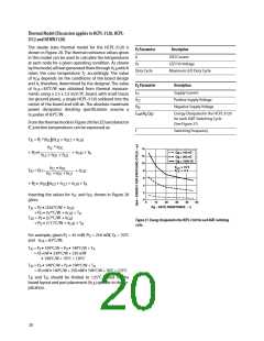
θ
= 443 °C/W
LD
ꢀ T ꢀ =ꢀ LEDꢀjunctionꢀtemperatureꢀ
ꢀ T ꢀ =ꢀ detectorꢀICꢀjunctionꢀtemperatureꢀ
JD
JE
T
T
JD
JE
ꢀ T ꢀ =ꢀ caseꢀtemperatureꢀmeasuredꢀatꢀtheꢀcenterꢀofꢀtheꢀpackageꢀbottomꢀ
C
θ
= 467 °C/W
θ
= 136 °C/W
DC
LC
ꢀ q ꢀ =ꢀ LED-to-caseꢀthermalꢀresistanceꢀ
LC
T
C
ꢀ q ꢀ =ꢀ LED-to-detectorꢀthermalꢀresistanceꢀ
LD
ꢀq ꢀ =ꢀ detector-to-caseꢀthermalꢀresistanceꢀ
DC
θ
= 8ꢀ °C/W*
CA
ꢀq ꢀ =ꢀ case-to-ambientꢀthermalꢀresistanceꢀ
CA
ꢀꢀꢀ*q ꢀwillꢀdependꢀonꢀtheꢀboardꢀdesignꢀandꢀtheꢀplacementꢀofꢀtheꢀpart.
CA
T
A
Figure 28. Thermal model.
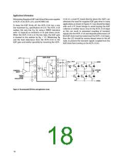
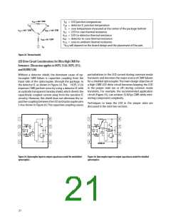
LED Drive Circuit Considerations for Ultra High CMR Per-
formance. (Discussion applies to HCPL-3120, HCPL-J312,
and HCNW3120)
perturbationsꢀinꢀtheꢀLEDꢀcurrentꢀduringꢀcommonꢀmodeꢀ
transientsꢀandꢀbecomesꢀtheꢀmajorꢀsourceꢀofꢀCMRꢀfailuresꢀ
forꢀaꢀshieldedꢀoptocoupler.ꢀTheꢀmainꢀdesignꢀobjectiveꢀofꢀ
aꢀhighꢀCMRꢀLEDꢀdriveꢀcircuitꢀbecomesꢀkeepingꢀtheꢀLEDꢀ
inꢀ theꢀ properꢀ stateꢀ (onꢀ orꢀ off)ꢀ duringꢀ commonꢀ modeꢀ
transients.ꢀForꢀexample,ꢀtheꢀrecommendedꢀapplicationꢀ
circuitꢀ(Figureꢀ25),ꢀcanꢀachieveꢀ25ꢀkV/µsꢀCMRꢀwhileꢀmini-
mizingꢀcomponentꢀcomplexity.
Withoutꢀ aꢀ detectorꢀ shield,ꢀ theꢀ dominantꢀ causeꢀ ofꢀ op-
tocouplerꢀ CMRꢀ failureꢀ isꢀ capacitiveꢀ couplingꢀ fromꢀ theꢀ
inputꢀsideꢀofꢀtheꢀoptocoupler,ꢀthroughꢀtheꢀpackage,ꢀtoꢀ
theꢀdetectorꢀICꢀasꢀshownꢀinꢀFigureꢀ29.ꢀTheꢀꢀꢀꢀꢀHCPL-3120ꢀ
improvesꢀCMRꢀperform-anceꢀbyꢀusingꢀaꢀdetectorꢀICꢀwithꢀ
anꢀopticallyꢀtransparentꢀFaradayꢀshield,ꢀwhichꢀdivertsꢀtheꢀ
capacitivelyꢀcoupledꢀcurrentꢀawayꢀfromꢀtheꢀsensitiveꢀICꢀ
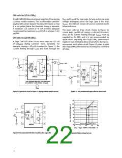
circuitry.ꢀHowever,ꢀthisꢀshieldꢀdoesꢀnotꢀeliminateꢀtheꢀca-
pacitiveꢀcouplingꢀbetweenꢀtheꢀLEDꢀandꢀoptocouplerꢀpinsꢀ
5-8ꢀasꢀshownꢀinꢀFigureꢀ30.ꢀThisꢀcapacitiveꢀcouplingꢀcausesꢀ
Techniquesꢀ toꢀ keepꢀ theꢀ LEDꢀ inꢀ theꢀ properꢀ stateꢀ areꢀ
discussedꢀinꢀtheꢀnextꢀtwoꢀsections.
C
1
3
ꢀ
4
8
7
6
5
1
3
ꢀ
4
8
7
6
5
LEDO1
C
C
C
C
LEDP
LEDP
C
LEDO3
LEDN
LEDN
SHIELD
Figure 29. Optocoupler input to output capacitance model for unshielded
optocouplers.
Figure 30. Optocoupler input to output capacitance model for shielded
optocouplers.
21

 AVAGO [ AVAGO TECHNOLOGIES LIMITED ]