FSK/ASK Demodulator
and Data Filter
The signal coming from the RSSI amplifier is converted into the raw data signal by the
ASK/FSK demodulator. The operating mode of the demodulator is set via the bit
ASK/_FSK in the OPMODE register. Logic ‘L’ sets the demodulator to FSK, applying ‘H’
to ASK mode.
In ASK mode, an automatic threshold control circuit (ATC) is used to set the detection
reference voltage to a value where a good signal-to-noise ratio is achieved. This circuit
effectively suppresses any kind of inband noise signals or competing transmitters. If the
S/N (ratio to suppress inband noise signals) exceeds 10 dB, the data signal can be
detected properly.
The FSK demodulator is intended to be used for an FSK deviation of 10 kHz ? ꢀf ?
100 kHz. In FSK mode the data signal can be detected if the S/N (ratio to suppress
inband noise signals) exceeds 2 dB. This value is guaranteed for all modulation
schemes of a disturber signal.
The output signal of the demodulator is filtered by the data filter before it is fed into the
digital signal processing circuit. The data filter improves the S/N ratio as its passband
can be adopted to the characteristics of the data signal. The data filter consists of a
1st-order highpass and a 2nd-order lowpass filter.
The highpass filter cut-off frequency is defined by an external capacitor connected to Pin
CDEM. The cut-off frequency of the highpass filter is defined by the following formula:
1
fcu_DF = ----------------------------------------------------------
2 P ꢂ P 30 kꢁ P CDEM
In self-polling mode, the data filter must settle very rapidly to achieve a low current con-
sumption. Therefore, CDEM cannot be increased to very high values if self-polling is
used. On the other hand, CDEM must be large enough to meet the data filter require-
ments according to the data signal. Recommended values for CDEM are given in the
electrical characteristics.
The cut-off frequency of the lowpass filter is defined by the selected baud-rate range
(BR_Range). The BR_Range is defined in the OPMODE register (refer to section ‘Con-
figuration of the Receiver’). The BR_Range must be set in accordance to the used baud
rate.
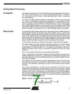
The T5743 is designed to operate with data coding where the DC level of the data signal
is 50%. This is valid for Manchester and Bi-phase coding. If other modulation schemes
are used, the DC level should always remain within the range of VDC_min = 33% and
V
DC_max = 66%. The sensitivity may be reduced by up to 2 dB in that condition.
Each BR_Range is also defined by a minimum and a maximum edge-to-edge time
(tee_sig). These limits are defined in the electrical characteristics. They should not be
exceeded to maintain full sensitivity of the receiver.
Receiving
Characteristics
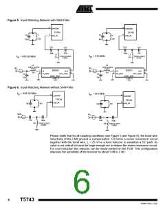
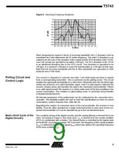
The RF receiver T5743 can be operated with and without a SAW front-end filter. In a
typical automotive application, a SAW filter is used to achieve better selectivity. The
selectivity with and without a SAW front-end filter is illustrated in Figure 8. This example
relates to ASK mode and the 300-kHz bandwidth version of the T5743. FSK mode and
the 600-kHz bandwidth version of the receiver exhibits similar behavior. Note that the
mirror frequency is reduced by 40 dB. The plots are printed relatively to the maximum
sensitivity. If a SAW filter is used, an insertion loss of about 4 dB must be considered.
8
T5743
4569A–RKE–12/02

 ATMEL [ ATMEL ]