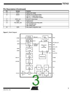
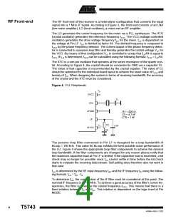
T5743
Analog Signal Processing
IF Amplifier
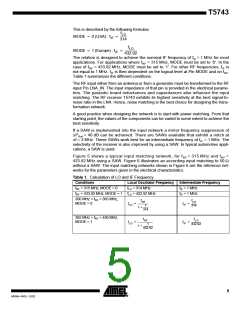
The signals coming from the RF front-end are filtered by the fully integrated 4th-order IF
filter. The IF center frequency is fIF = 1 MHz for applications where fRF = 315 MHz or
fRF = 433.92 MHz is used. For other RF input frequencies refer to Table 1 to determine
the center frequency.
The T5743 is available with two different IF bandwidths. T5743P3, the version with
BIF = 300 kHz, is well suited for ASK systems where Atmel’s PLL transmitter U2741B is
used. The receiver T5743P6 employs an IF bandwidth of BIF = 600 kHz. Both versions
can be used together with the U2741B in ASK and FSK mode. If used in ASK applica-
tions, it allows higher tolerances for the receiver and PLL transmitter crystals. SAW
transmitters exhibit much higher transmit freqeuncy tolerances compared to PLL trans-
mitters. Generally, it is necessary to use BIF = 600 kHz together with such transmitters.
RSSI Amplifier
The subsequent RSSI amplifier enhances the output signal of the IF amplifier before it is
fed into the demodulator. The dynamic range of this amplifier is DRRSSI = 60 dB. If the
RSSI amplifier is operated within its linear range, the best S/N ratio is maintained in ASK
mode. If the dynamic range is exceeded by the transmitter signal, the S/N ratio is
defined by the ratio of the maximum RSSI output voltage and the RSSI output voltage
due to a disturber. The dynamic range of the RSSI amplifier is exceeded if the RF input
signal is about 60 dB higher compared to the RF input signal at full sensitivity.
In FSK mode the S/N ratio is not affected by the dynamic range of the RSSI amplifier.
The output voltage of the RSSI amplifier is internally compared to a threshold voltage
V
Th_red. VTh_red is determined by the value of the external resistor RSens. RSens is con-
nected between Pin SENS and GND or VS. The output of the comparator is fed into the
digital control logic. By this means it is possible to operate the receiver at a lower
sensitivity.
If RSens is connected to GND, the receiver operates at full sensitivity.
If RSens is connected to VS, the receiver operates at a lower sensitivity. The reduced sen-
sitivity is defined by the value of RSens, the maximum sensitivity by the signal-to-noise
ratio of the LNA input. The reduced sensitivity depends on the signal strength at the out-
put of the RSSI amplifier.
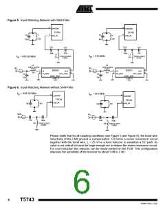
Since different RF input networks may exhibit slightly different values for the LNA gain,
the sensitivity values given in the electrical characteristics refer to a specific input
matching. This matching is illustrated in Figure 6 and exhibits the best possible
sensitivity.
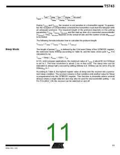
RSens can be connected to VS or GND via a microcontroller. The receiver can be
switched from full sensitivity to reduced sensitivity or vice versa at any time. In polling
mode, the receiver will not wake up if the RF input signal does not exceed the selected
sensitivity. If the receiver is already active, the data stream at Pin DATA will disappear
when the input signal is lower than defined by the reduced sensitivity. Instead of the
data stream, the pattern according to Figure 7 is issued at Pin DATA to indicate that the
receiver is still active (see also figure 34).
Figure 7. Steady L State Limited DATA Output Pattern
DATA
t
t
DATA_L_max
DATA_min
7
4569A–RKE–12/02

 ATMEL [ ATMEL ]