T5743
This is described by the following formulas:
fLO
MODE = 0 (USA) : fIF = ---------
314
fLO
MODE = 1 (Europe) : fIF = -----------------
432.92
The relation is designed to achieve the nominal IF frequency of fIF = 1 MHz for most
applications. For applications where fRF = 315 MHz, MODE must be set to ‘0’. In the
case of fRF = 433.92 MHz, MODE must be set to ‘1’. For other RF frequencies, fIF is
not equal to 1 MHz. fIF is then dependent on the logical level at Pin MODE and on fRF.
Table 1 summarizes the different conditions.
The RF input either from an antenna or from a generator must be transformed to the RF
input Pin LNA_IN. The input impedance of that pin is provided in the electrical parame-
ters. The parasitic board inductances and capacitances also influence the input
matching. The RF receiver T5743 exhibits its highest sensitivity at the best signal-to-
noise ratio in the LNA. Hence, noise matching is the best choice for designing the trans-
formation network.
A good practice when designing the network is to start with power matching. From that
starting point, the values of the components can be varied to some extent to achieve the
best sensitivity.
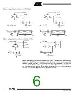
If a SAW is implemented into the input network a mirror frequency suppression of
ꢀPRef = 40 dB can be achieved. There are SAWs available that exhibit a notch at
ꢀf = 2 MHz. These SAWs work best for an intermediate frequency of fIF = 1 MHz. The
selectivity of the receiver is also improved by using a SAW. In typical automotive appli-
cations, a SAW is used.
Figure 5 shows a typical input matching network, for fRF = 315 MHz and fRF
=
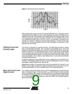
433.92 MHz using a SAW. Figure 6 illustrates an according input matching to 50 ꢁ
without a SAW. The input matching networks shown in Figure 6 are the reference net-
works for the parameters given in the electrical characteristics.
Table 1. Calculation of LO and IF Frequency
Conditions
Local Oscillator Frequency
Intermediate Frequency
fIF = 1 MHz
fRF = 315 MHz, MODE = 0
fLO = 314 MHz
fRF = 433.92 MHz, MODE = 1 fLO = 432.92 MHz
fIF = 1 MHz
300 MHz < fRF < 365 MHz,
MODE = 0
f
f
RF
1
LO
f
f
= -------------------
f
f
= ---------
LO
LO
IF
IF
314
1 + ---------
314
365 MHz < fRF < 450 MHz,
MODE = 1
f
f
RF
LO
= ---------------------------
= -----------------
1
1 + -----------------
432.92
432.92
5
4569A–RKE–12/02

 ATMEL [ ATMEL ]